The Dogson-2 Telescope
Fast Find >> Mirror,
Pitch,
Pitch
lap, Polishing cradle, Polishing
strokes, Stroke speed, MOT,
Diagonal,
Leave it sphere?, TheAlt-Alt
option, Polishing out pits, Testing,
The
laser test,
The Jerry test,
Ronchi test,
More
Ronchi,
The star test, Rez test,
Aluminizing,Collimation,
Sky
compass,
Storage,
Foreleg, Focusers,
Glow
finder, Cleaning,
Modernity,
Null
test, Reflectivity, Coatings,
A
finder 'scope,

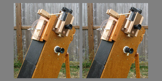
a stereo pair
You're at: https://57296.neocities.org/dog-2.html
(Last worked on: October 25th,
2022.)
>This page attempts to confine
itself to just the making, accessorizing and the using --of a Dogson telescope<
* For a more complete and traditional background
on ATMing, try the following link: https://stellafane.org/tm/index.html
For an excellent overview of amateur astronomy, see:
https://www.handprint.com/ASTRO/atm.html
Hold "Ctrl" and tap "+" for larger text.

* To design the Dogson I started with the standing and
the stool sitting eyeball height of young people and myself, then built
an affordable, do-able telescope around that dimension: one that's (hopefully)
inherently stable, vibration free, easy to transport, simple to set up
and collimate, intuitive to steer around and adequate for the less than
ideal skies most of us live beneath. I ended up with traditional (6" x
f/8 to f/9) optics.
It turned out to be a 5.75" by f/8.74 (as
masked) with 75% illumination (secondary limited) to the edge of a
.85 degree (51 minute) field of view, and is quite usable for a (one magnitude
dimmer at the edge) 1.25 degree field with an affordable (say: $40) 32mm
eyepiece.
For wider angle observing, I've got a pair of Russian
20/80 binoculars (2.75 degrees) and a pair of excellent
10x50 Brunton binoculars (6+ degrees, purchased at a close-out price).
A wee bit of disjointed
ATMing & observing philosophy:
(more of this sort of
talk on page-1)
* An eye full of stars is an eye full of stars, whether
seen through a honking "richest field" telescope or a blackened toilet
paper tube. The point is to pay attention, know or learn what you're looking
at, to log what you can of it ("progress made good"), and to possibly make
a discovery --but without turning an enjoyable avocation into a miserable
pain-in-the-ass (I'm still working on that part :-) and letting astronomy
overload your life. Since observing is mostly done in the dark, damp, cold
hours of the night, it can easily get out of proportion and become an experience
that you tend to postpone. Have goals, but reasonable ones. As for traveling
to dark sites, will that be sustainable in the long term, for the doing
of personal astronomy? "Happiness is in your own back yard."
* Where I live, it's particularly chilly and damp at
night, often with but brief clear sky opportunities. Lately I've been wondering
if I should take another stab at celestial photography --and study my astrographs
instead of standing out there in the cold (then use my good Dogson for
a closer look at a thing or two in particular). (In that regard, I finally
broke down and tried doing some image stacking, which gave me significantly
more magnitude reach with just a few frames.)
* But there will always be stuff that's beyond the
reach of your eye and your instruments. Instead of straining at your limits,
simply pay good and accurate attention to what's at hand. Useful and even
innovative work (VSOing, meteor counts, binaries, comets, Lunar events)
can be done with a log book/device, method, clock, and minimal observing
equipment.
* As to telescopes, Nils Olof Carlin's suggested collimation
tolerances imply that the making of a successful telescope can be a fairly
casually executed project --or it can become a bit of a struggle to maintain
your instrument within tight error limits. (If your telescope is well made
(ie: rigid) then even a short focus 'scope might only need a little tweak
at the start of each session, after which the alignment will hold as you
swing it about.)
Carlin suggests that your scope's optical tube assembly
("OTA") and the alignment of its optics should be within the following
tolerances --through to the lateral drift of its prime focus (regardless
of the objective's diameter):
f/4 = +/-0.7mm; f/4.5 = +/-1mm; f/5 = +/-1.4mm;
f/6 = +/-2.4mm; f/8 = +/-5.5mm; f/10 = +/-11mm
Comparatively, then: the build quality and maintenance
of an f/8 or longer Newtonian scope appears to be a "walk in the park"
--if its aperture doesn't exceed about 8 inches or 200mm. (Any larger/longer
and you'll be stumbling around in the dark with a slippery wet step-stool
or ladder.)
* See here for
more about choosing an ATM project.
** Another consideration in the decision to make,
buy or repurpose optics for a telescope --is that the grind and polish
ATM will be working with an assortment of unusual substances. Aside from
silvering chemistry (which few of us any longer engage in), there's glass
dust, fine grinding and polishing compounds. You want to avoid scattering,
inhaling and ingesting these items, or letting kids play in or have access
to the area. You also want to avoid flushing coarser grinding compounds
and sludge/slurry down household drains --where it might clog up.
The polishing compound sold as "cerium oxide" is special
in that it's made up of variable components, one of which might be radioactive
(as is the batch I'm using). Here's the list from an old MSDS sheet:
"Rare Earth Oxide": 30% - 65% (presumably: that's
the nominal cerium oxide --Craig)
Calcium Oxide:
10% - 15%
Strontium Oxide:
1% - 6%
Alumina Silicate:
1% - 40%
Fluorides:
4% - 10%
Silica:
2%
* The stuff I bought and used was tan colored and it
really made my Geiger counter click. Clearly, this is a poorly defined
and controlled substance. Though not listed, the radioactive component
is sometimes said to be thorium. My sample was a heavy beta emitter. [I
don't know if there's any alpha.]
But there's good news on that. "Got Grit" sells "white"
cerium oxide. Jerry Oltion kindly sent me a sample and I got no clicks
above normal background here.
** As you'll see by my polishing and figuring notes,
I found my 6 inch mirror damnably difficult to make --at least this first
time through the course. Such problems as I experienced are usually written
off to the errors of newbie ATMers, but an experienced and very active
voice at the Eugene, Oregon club advises beginners to start instead with
a shorter focus 8 or 10 inch mirror. He recounts that, despite his many
[exemplary, I'll add] telescope project successes since, his only failed
and abandoned mirror was a traditional 6 inch. More-over, he's not seen
but one really good 6" mirror. (I made a good spherical 8 inch x f/10 mirror
60 years ago with no special problems.)
So at this point, I've made a "good" 6 inch mirror
(by my humble standards), but only after 76 hours of polishing(!) --work
which should have taken me about 6 hours. Only the making of my second
6 inch mirror will demonstrate if I've finally got the small mirror process
bolted down.
Never-the-less, I'm presenting what appear to be the
methods, tools and materials which worked.
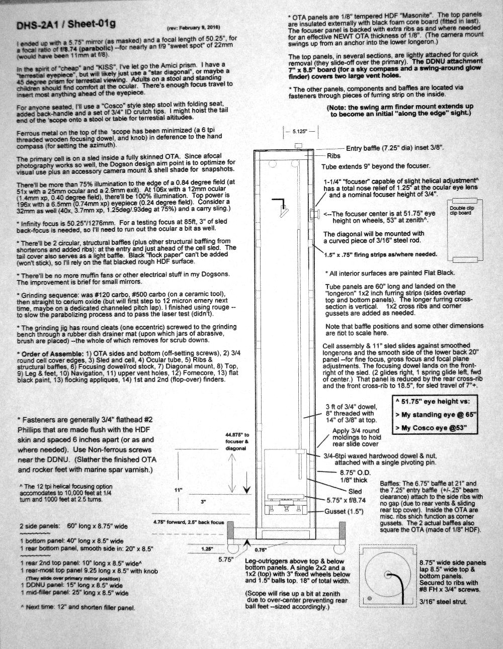
* Here's the main page of my as-built
drawings for Dog-2 (click to enlarge):
"Dog-3" will probably follow a simpler construction
plan, but it will still be about 6 inches by f/8
(Since this plan and these photos, I've gone to 5"
"wheels" (which only "turn" with the 'scope) plus
one inch extensions under the over-center balls --for
better ground clearance on rough terrain.)
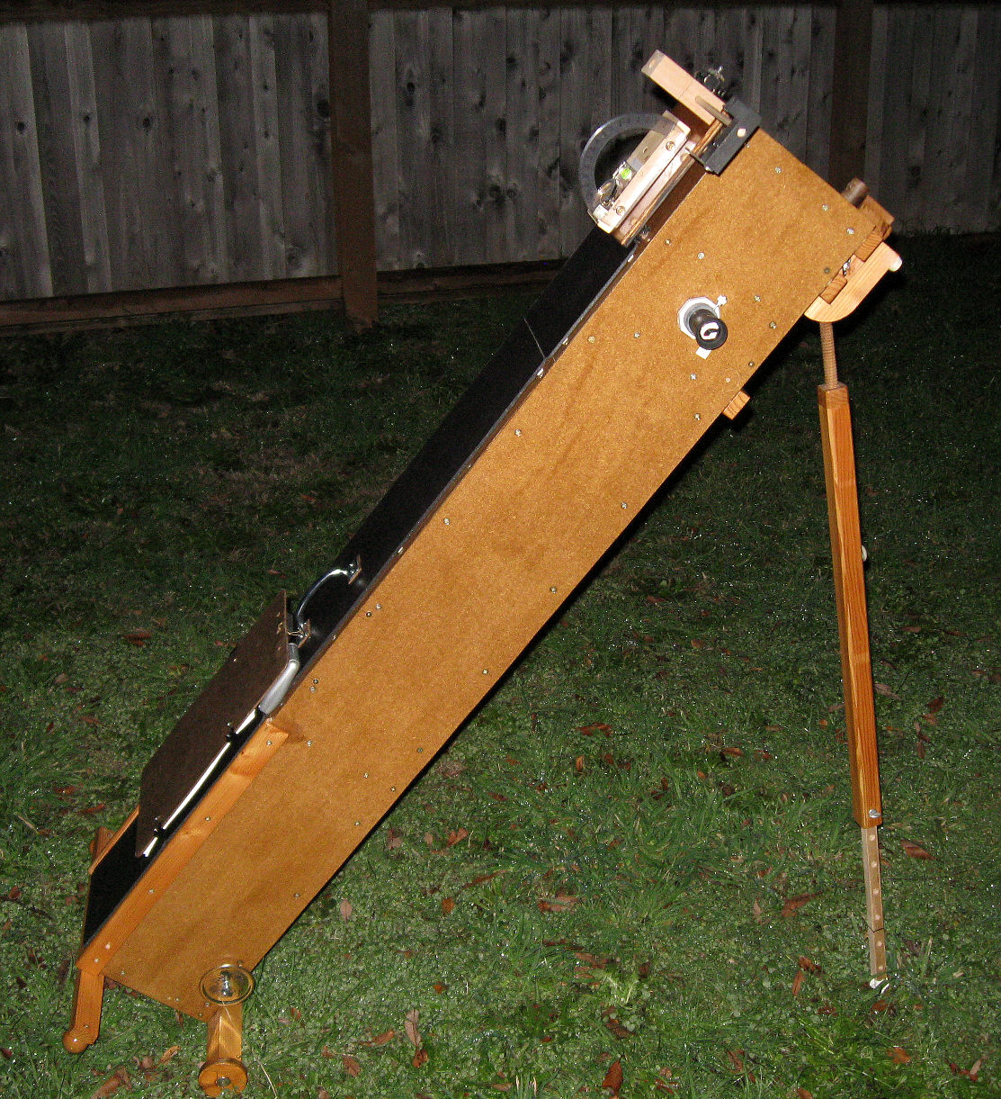
(Click these images to enlarge them.) (Earlier
version.)
 * Let's address the Dogson design/concept's deficiencies
(that
I'm aware of):
* Let's address the Dogson design/concept's deficiencies
(that
I'm aware of):
~ Chief among them is low altitude
(below 30 degrees) sky and terrestrial observational performance. You can
hoist the butt end up onto a stool or table, but then the balance and vibration
aren't good.
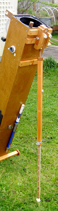
~ Dog-2's low altitude accommodation
was somewhat designed around a Cosco brand step stool that we own. With
added crutch tip feet (the small original feet sunk into the ground), it
seemed ideal to use with this scope --sitting, small kids stepping up,
"butt hauling" (with the seat flipped up) for the range of 15 to 30 degrees,
and down to zero with the alternate fore-leg.
~ While (screw) jacking the Dogson
up and down in altitude goes swimmingly, some won't like turning this 'scope
in azimuth --with its non-turning wheels dragging in the dirt (and there's
a wee bit of backlash to compensate for).
~ By today's strut and string 'scope
standards, at 30 pounds it's heavy for a 6 inch telescope, though maybe
not when compared to other long focus, closed tube scopes.
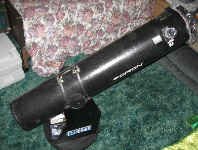 I had on loan a typical, commercial, 8 inch Dobson (an
early Orion). The tube assembly with mirrors weighs 24 pounds and the base
weighs 25 pounds. Were I to scale my Dogson up to use an 8 inch mirror,
it would weigh 71 pounds and I'd need to stand on a step stool at times.
(This old Orion's tube is only 9 inches inside diameter and a trim ring
at the mouth reduces that to 8-3/8 inches, so this scope should have been
a bit larger and heavier --as are Orion's later 8" Dobs.)
I had on loan a typical, commercial, 8 inch Dobson (an
early Orion). The tube assembly with mirrors weighs 24 pounds and the base
weighs 25 pounds. Were I to scale my Dogson up to use an 8 inch mirror,
it would weigh 71 pounds and I'd need to stand on a step stool at times.
(This old Orion's tube is only 9 inches inside diameter and a trim ring
at the mouth reduces that to 8-3/8 inches, so this scope should have been
a bit larger and heavier --as are Orion's later 8" Dobs.)
~ The Dogson is not a scope for
swinging about and earning your Messier certificate. It's for picking and
finding a target/object, studying it, and maybe shooting an afocally
coupled snapshot (if the object is bright enough).
~ So far, I can't think of any way
to make this "stick-in-the-mud" telescope track.
~ Then there's the
"Dobson hole": that difficulty when observing near the zenith, since aiming
at and following a star with an Alt-Az mounted 'scope requires nearly a
180 degree swing-around in azimuth. However, the Dogson design lends itself
to a recent solution demonstrated by Mel Bartels: the "Alt-Alt-Az" mount
(see the February 2019 issue of Sky & Telescope for its Workbench article
by Jerry Oltion). Instead of rigidly mounting the Dogson's over-center
back feet to the OTA, the cross-bar might instead be attached at its center,
via a lateral rocker bearing (with limited range and considerable, adjustable
friction). The downsides of doing so:
> Don't let go of the OTA until its foreleg is securely repositioned and
planted.
> The DDNU (setting circle platform)'s calibration is lost when resorting
to secondary altitude travel. However, the assumption is that the observer
is already close to or tracking the quarry --and/or: for the experienced
astronomer, the sky is his/her chart/program and no recourse to co-ordinates
is required.
* Dogson Advantages:
~ As a one-hand lift, one-piece
telescope (not counting a stool and kneeling pad), you can take it and
go (the separately stored mirror already having been slipped into place).
(I only "go" out into the side yard of our home.)
~ At astronomical altitudes (30
degrees and above) the OTA/tube is itself two parts of a steady tripod
to the ground. There are no vibrations, no shaking when you adjust the
focus, and no balance problem when you use a large eyepiece or mount a
camera. If you're tired, rest an arm on the scope.
~ By using the Cosco step stool/chair
or a typical plastic garden chair (which has about an 8 inches lower seat),
an adult can comfortably observe from about 45 degrees of altitude to the
zenith. For the range of 30 to 45 degrees, an adult who's able to use a
kneeling pad or a low stool is accommodated.
~ The mirror is securely held captive,
but easily removed with a single thumbscrew --such that it is convenient
to store the mirror at outside temperatures (face down in a cheap, desiccated,
air
tight container). There's a mark on the mirror's periphery so I can
always re-install it the same way.
~ The primary mirror cell rides
on a sled which can be moved to adjust fine focus and/or to accommodate
gross prime focus changing accessories (like maybe an erecting Amici prism
or a Barlow fore-lens) and to accommodate close subjects (down to 100 feet,
and more such accommodation can easily be designed into the Dogson).
This gross focus adjustment range can also make up
for a maker's mirror that fell short or long of its target focal length,
without having to bore another focuser hole.
~ The "focuser" also focuses a bit
--helically, possibly to estimate distances in the 1000 to 10,000 foot
range.
~ Despite not having a rocker box,
this Dogson does have setting circles
~ It also has a swing
out (and swing around to the other side, if desired) lightweight finder
--
~ --plus a swing-up camera mount.
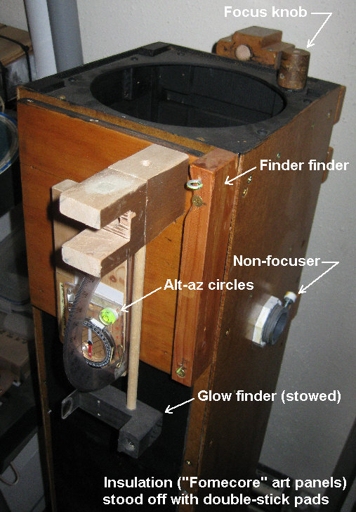
~ Since the tube is square, it's easy
to mount accessories and features like those black "Fomecore" top-side
insulation panels, internal baffles, the cell sled,
sled tension arms, the secondary strut positioning "float
block", a plumbing parts
focuser, a slide-off mirror
access
panel, a frame attached
Dog leg and feet,
a swing-out finder and the DDNU navigation platform.
Focuser detail
(The set line and bumper piece is for laterally positioning
an afocally coupled, swing-up hand camera.)
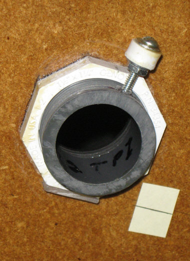
This limited helical focuser is cobbled from plumbing
parts (you can see the inside detail here). It can
hold the waist banded, short barreled 32mm Celestron eyepiece in the below
image. However, except for range estimation (1000 to 10,000 feet), such
slow focusing adjustment isn't needed. Given smooth barreled eyepieces
and the cell-sled approach to primary focusing, one can easily do fine
focusing with less than parfocal eyepieces by simply turning and push-pulling
them in a simple "eyepiece holder" like the below pictured plumbing item:
a 1-1/2" to 1-1/4" ABS, male trap adapter (under $2, and thanks to Richard
Berry for the suggestion). The nut adjustment and washer produces any desired
degree of buttery smooth grip upon a standard (smooth) eyepiece barrel.
(Simply add thin O-rings to your eyepieces to make them approximately parfocal.)

A few 1-1/4 inch choices
Rack and pinion focuser, Plumber's delight eyepiece
holder, Smooth barrel eyepiece, Celestron's waisted 32mm eyepiece
The traditional focuser at left is usually fitted so
as to allow an inch of inward travel. As such, and with an eyepiece fully
seated, the top of its tube stands an eyepiece 4 inches off of a round
tube, and 4-1/4" off a square tube. Using a low profile helical or friction
focuser like that ABS plumbing item can bring the eyepiece in to only an
inch and a half (leaving a bit of inward travel), which in turn allows
a significant reduction in diagonal size/obstruction, diagonal weight and
potential vibration problems. (Again: that plumbing item is a no-go with
a waisted eyepiece barrel.)
Modern Times:
* Yes, I'm aware of "goto" 'scopes and the amazing
"Safari" ($20 --!) application for i-Pads --which I've played with for
a few minutes, and which affordably turns any telescope into a goto instrument
--or buy a long focus optic for the i-Pad, which then itself becomes a
navigating astrophotographic telescope --!-- (but you might then want to
mount it onto a good tripod).
* Most everyone we know, young and old, has a hand-held
computer/cell phone/Internet device --except ourselves. My understanding
is that once you've acquired an I-thing (used ones are affordable or free)
with GPS and inertial/gyroscopic capabilities --and have downloaded a Safari-like
sky program, it can then be operated (sans any updates) without a communications
contract. But --the Luddite in me says: "whoa".
* But what do I know? Our great-grandchildren had to
tell us about WiFi a few years back. We stood there like amazed bush people
as they sucked the Internet out of thin air. We only pack a bottom-feeder
CDMA Tracfone (under $10/month) for hello-goodbye voice and have no Internet
access at home --which would cost us $55/month --more than water and sewer!--
unless part of a $90/month "bundle". (We remember $10/month for an Internet
connection.) So instead, we use a pair of Chromebooks
to cadge free public WiFi.
Some of the "passions of our times" (like posting this
page to the Internet) we must share --even embrace (and ain't HTML grand?),
but I feel alienated from things that are price fixed and far beyond my
understanding. (This is really more about my own struggles here with modernity
--than any retro advocacy.)
The Mirror
The 6 inch mirror that I made for my "Dogson-2"
telescope has only been my 2nd time at grinding and polishing in 60 years.
My first mirror was an 8 inch x f/10, which I finished to a spherical figure.
To begin: * If the back of your
blank isn't smooth and clear, make it so --by grinding with #120 and then
#500 grit against flat glass or ceramic tile. Follow that up with some
sleazy polishing technique --like #500 grit against a plastic tool --whatever
works to make it transparent.
* Next: put a good 45 degree bevel
(or "chamfer") around the peripheries of the back and the face of the mirror.
Yes: you'll be initially losing some diameter --as much as 1/4 inch (1/8"
bevel), but you get some back as you grind, and you want enough bevel so
as not to be doing it twice. I used a typical, traditional, two-sided (rough
and fine), carborundum sharpening stone --and the fine side seemed fine
enough. (This beveling work takes a while.)
~ When cleaning my finished, polished
mirror in preparation to send it in for aluminizing, I was unable to simply
wash off a ring of cerium oxide (polishing agent) which was crusted onto
the bevel. I had to go around the bevel again with the carborundum stone
--holding the stone such that I could not possibly scratch the mirror.
Grinding: The grinding part of this
project was pretty straight forward, plus I benefited from good advice
by my circle of astronomy/ATM friends.
I also gathered what I could from the literature in
our library and summarized it:
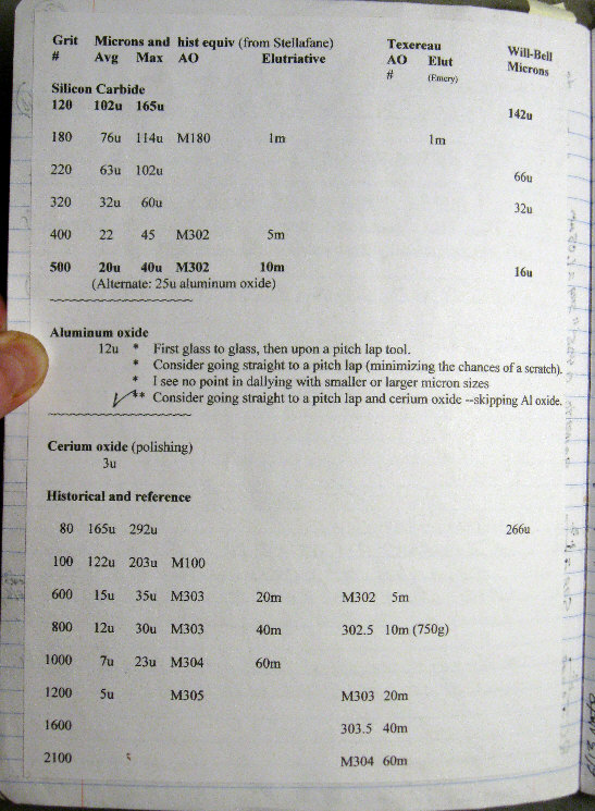 * Unlike 60 years ago when I made my first mirror, and
per suggestions from others in my astronomy e-group, I short-circuited
the little incremental abrasive steps by starting with #120 grit (102 micron
average, 165u max), then #500 (20 micron average diameter, 40 micron max
--quite a jump) --and straight to polish after that. The old timers didn't
have today's "micron" grits and generally went from #600 grit (12u average,
30u max) to polish. I wanted to find out how tough it is to polish out
#500 grit pits --with today's advantage of using cerium oxide.
* Unlike 60 years ago when I made my first mirror, and
per suggestions from others in my astronomy e-group, I short-circuited
the little incremental abrasive steps by starting with #120 grit (102 micron
average, 165u max), then #500 (20 micron average diameter, 40 micron max
--quite a jump) --and straight to polish after that. The old timers didn't
have today's "micron" grits and generally went from #600 grit (12u average,
30u max) to polish. I wanted to find out how tough it is to polish out
#500 grit pits --with today's advantage of using cerium oxide.
Answers:
~ The rough and fine grinding both
went fast --maybe too fast for good control. I spent more time gauging
my progress (ended up using automotive leaf gauges and a truly straight
[hard to find] steel rule for the sagitta) --
~ --and trying to judge when #500
pits had vanquished the #120 pits. (Which was fairly easy, after I made
a glass microscope slide with #120 grind on one end and #500 grind on the
other --for microscopic comparison.)
~ You can switch to "wet testing"
the mirror (plain water is best) by reflection (an AA battery flashlight
next to your eye) shortly after starting the #500 grit grind.
~ Be very sure to do the "pencil"
or "felt tip marker" test for contact --before calling it quits with your
finest fine grind. (Simply mark up the mirror, then see if a few strokes
cleans your marks off evenly.)
~ Yes: it is plenty tough to
polish #500 grit pits out of Pyrex --something
like 20 hours to pass traditional microscopic inspection. The alternative
is to use a final, very fine grind with "micron grit" --maybe 12 micron.
However, this is the point at which your mirror is most vulnerable to getting
scratched (one of the reasons why I skipped using micron grits). Next time
I'm going to try following the #500 grit with 12 micron grit on a dedicated
pitch lap --which "will not scratch".
* There were many little questions and decisions:
~ How much grit per "wet" (1/8th
teaspoon);
~ How long is a "wet" (go by ear,
and you can add drops of water to extend it a bit).
~ How hard to bear down during rough
grinding (as hard as you can comfortably sustain without getting sloppy,
which was about 20 pounds total pressure and mirror weight for me).
~ How wet is a wet (sluice off the
tool and mirror in your plastic bucket, leaving both wet).
~ How wide & long is the "hogging"
stroke (what you're comfortable with -maybe "4/5ths".
Don't tip the mirror.)
~ How close to the RC (radius of
curvature) should I rough grind (1% long, since the "1/3rd
W" "maintenance stroke" pretty much stops RC progress when you need
to (during fine grind or polish, and assuming the use of a polishing cradle).
You can "hog" #500 grit until the focus is about 0.5% longer than your
target.
* Again: For a more complete background on ATMing,
follow this link:
https://stellafane.org/tm/index.html
Polishing:
* I repeatedly experienced the common problem of a
blankety-blank "turned down edge" (TDE) plus it
had a stubbornly oblate figure --even with an undersized lap (MOT).
I've read and heard that a TDE is especially common for beginners and for
those who make longer focus 6 inch mirror --for over 100 years, and maybe
for 300 years. I think it's time to get a better consensus as to what
causes a TDE and what doesn't.
** For sure: since the mirror's figure at the edge
of a mirror must "go around the corner", there will always be a bit of
TDE. One ATMer routinely flats and frosts it with fine grit, then paints
it flat black. Many others, some commercial, routinely mask off a wee bit
of TDE --perhaps using a metal band with a rolled edge. I mask
the edge with a black paper collar and a cut-to-pop-in-fit O-ring (thickness/diameter
as needed).
Fingers are often pointed at soft pitch laps as the
TDE culprit and one can imagine the mirror's leading edge plowing into
soft pitch. Mel Bartels and
others, however, can work with a relatively soft lap and not end up with
a serious TDE. Also, the periphery of my mirror was the last to polish
out (which is typical), so the TDE didn't develop because I was knocking
down the edge --but because I was deepening the slope of the central zones
(despite that it somehow remained oblate, overall), and/or the polishing
action wasn't getting to the edge (duh: since the edge spends half the
time over-hanging the lap).
Never-the-less, I slowly came to the realization that
my pitch was indeed too soft, which is at least a nuisance in that the
lap needs frequent trimming.
It also dawned on me that we needed a much better
way to gauge pitch hardness. Traditionally, one simply bends a small
piece or pushes his/her thumbnail into a sample, but touching, holding,
or the very work of pushing your thumbnail into it will heat and sharply
soften the pitch. (In India, ATMs try chewing a piece -!- but before you
write them off as primitives, I also have an account of that being the
practice in a pre-WW-2 optical lab here in the states.) Consequently, I
took a long detour in order to nail down the
hardness of
my pitch --against temperature.
While I suspected that I'd not have developed such
a horrible turned down edge with harder pitch, I first went (by stages)
to a 17% (1 inch) undersized lap (polishing with
mirror on top = MOT) to see if that alone (using my rather soft 58 minute
[plunge test] pitch lap) --might roll back a turned
down edge --without producing other problems. It didn't, and I've gotten
the impression that undersized and otherwise "mutilated" laps are a zone
problem making bad idea.
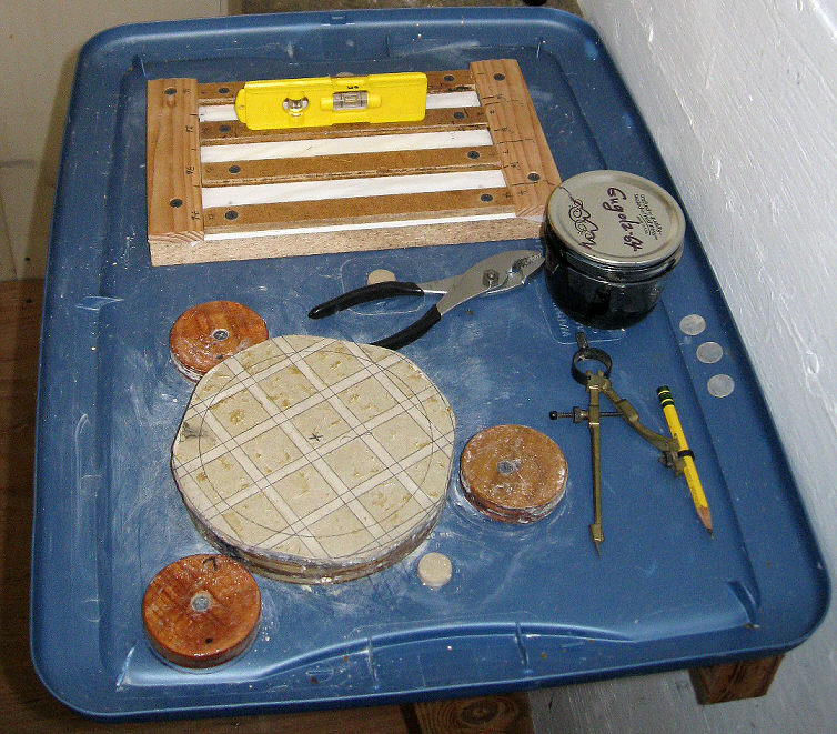
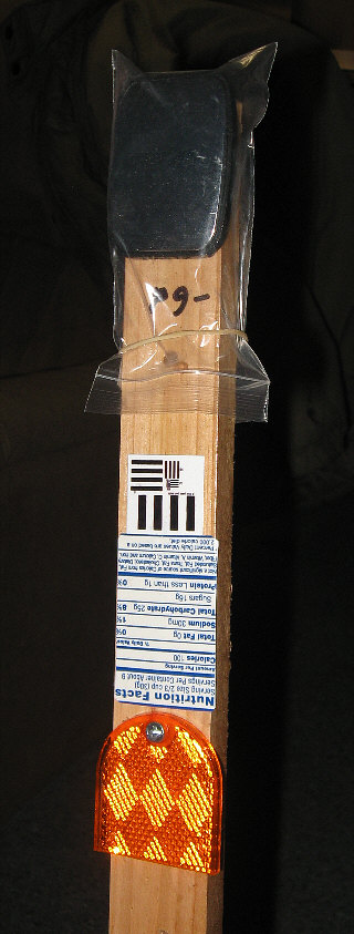
My pitch strip mold and grinding tool, marked for
a 6" lap with 1" tiles
--and the failed undersized lap effort (click
to enlarge)
* I eventually settled on using somewhat soft (166
minute plunge test) pitch --which is about the same viscosity/hardness
as (brand name) "Gulgolz-64", and I reduced my TDE with a 4/5th "W stroke".
Polishing Speed and Pressure
(11/8/2015)
I have to force myself to go slow and not bear down when
polishing. Developing good contact and drag (which "micro-faceted" tile
faces help) --has a natural effect of slowing the stroke speed. It does
seem that, to get the smoothest and most careful results, minimum pressure
and a slow rate of mirror travel (MOT, a maximum average
of 8 inches per second) are important.
The negative consequences which ATMs have experienced
by polishing "too fast" and the "strokes per second" or minute advice we
get on that matter must also be weighed against mirror size and stroke
length --since (obviously) a "1/3rd" W stroke per second with a 12 inch
mirror requires moving it twice as far per second than with a 6" mirror.
I've decided against blaming inertial tipping/plowing
and drag heating (unless polishing squeaky dry), but it seems intuitive
that if the "give" of pitch isn't fast enough for cerium oxide particles
to yield (when they snag into the pitch), then they might start to tumble
--in the fashion of grinding particles.
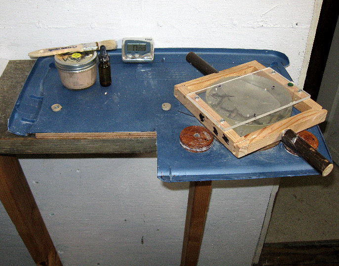
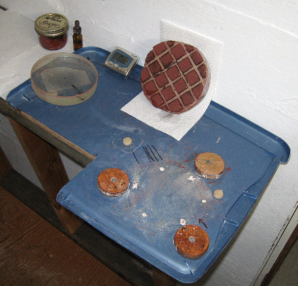
The Pitch
and checking the "hardness"/viscosity
(Click on these images to enlarge them.)
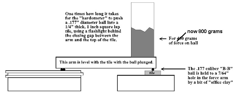
The 1/4" x 1" square pitch tiles are kept in a 68 degree
Fahrenheit water bath until tested and the room temperature (or that of
an enclosing box) is maintained at 68 as well (20 degrees centigrade).
What you see is a hardwood arm with two glued in BB bearings in the back
and a single test BB in the front --captive and located by a 7/64 inch
hole and a bit of "office tacky clay" (wonderful stuff). I added enough
lead shot to that tube such that the scale read 800 grams (with the arm
level).
For more about these tests, see here.
For more about my approach to making a small pitch
lap (ala Jean Texereau), see here.
 Not shown is the box I put this rig in, the ice chest
and 12v muffin fans which supplied and circulated cooling air, the HVAC
household thermostat, DPDT relay, 12 volt DC supply, nor the small 120v
lamp and dimmer switch which adjusts the rate at which the temperature
is brought up again. A programmable digital thermostat (the affordable
Lux brand) and a Coleman Peltier effect 12V cooler would have been better
choices, but I tend to use what's at hand.
Not shown is the box I put this rig in, the ice chest
and 12v muffin fans which supplied and circulated cooling air, the HVAC
household thermostat, DPDT relay, 12 volt DC supply, nor the small 120v
lamp and dimmer switch which adjusts the rate at which the temperature
is brought up again. A programmable digital thermostat (the affordable
Lux brand) and a Coleman Peltier effect 12V cooler would have been better
choices, but I tend to use what's at hand.
However: one can simply use the normal temperature
and environmental controls of the room the illustrated apparatus is located
in, making sure to keep the air moving for uniform temperature. The below
graph will help you compare a single plunge time that you've clocked
against my measurements (at least for the two brands of pitch I've tested)
such that you don't have to worry about what temperature spot on the graph
you use --just temperature uniformity (a fan and mid-day) and wait for
the pitch under test to arrive at a uniform temperature.
* Optical pitch is a rather viscous substance. My plunge
times for both Willmann-Bell "hard" pitch and Gulgolz-64 were running to
12 and 9 hours --at 68 degrees Fahrenheit with 400 grams of weight force.
Consequently, I switched to lead shot and doubled the plunging force to
a weight of 800 grams. That didn't simply halve the initial plunge times,
since the work performed in plunging the BB ball contributes to the local
temperature of the pitch. Results will always be peculiar to the test method
used, so try to replicate my test rig, develop methods and graphs of your
own, or use the test rig published in later editions of Jean Texereau's
book (see next item).
Update (10/05/2014): My 1957 copy
of Jean Texereau's "How To Make A Telescope" advocates the old thumbnail
pitch hardness test, but thanks to Jerry
Oltion, I've been alerted that later editions include simple plans
for making a pitch hardness/viscosity test rig:
 --which drives a kilogram weighted (total weight at the
point), steel rod into a polishing tool mounted pitch square for a period
of 5 minutes --after which the penetration depth is measured. The acceptable
depth range for mirrors between f/6 and f/12 is 0.02 to 0.24 inches (0.5mm
to 6.0mm) --at your work room temperature. The hardness goal is set at
.07 inch (1.8mm) of travel depth after 5 minutes. (Deep dish mirrors in
the f/3 to f/4 range have proven hard to work unless softer pitch is used
--perhaps a 0.31 penetration depth --at your work room temperature.)
--which drives a kilogram weighted (total weight at the
point), steel rod into a polishing tool mounted pitch square for a period
of 5 minutes --after which the penetration depth is measured. The acceptable
depth range for mirrors between f/6 and f/12 is 0.02 to 0.24 inches (0.5mm
to 6.0mm) --at your work room temperature. The hardness goal is set at
.07 inch (1.8mm) of travel depth after 5 minutes. (Deep dish mirrors in
the f/3 to f/4 range have proven hard to work unless softer pitch is used
--perhaps a 0.31 penetration depth --at your work room temperature.)
The penetrating tip is tapered to 14 degrees and its
tip is flattened back to a width of 0.04 inch (1mm), the details of which
will be found *here*
on Jerry's pages, since he built a Texereau tester.
Jerry also checked some new Gulgolz-64 pitch, finding
it to fall 0.021 inch at 68 degrees F. Earlier,
he'd sent me a sample of the same pitch and it corresponded to 247 minutes
on the
chart below when using my rig. That happens
to be the hardest pitch Texereau recommends for polishing and figuring
medium to long focus mirrors (at a work room temperature of 68 degrees
Fahrenheit).
Judging from my chart and the one in Texereau's newer
editions, this pitch would remain usable at 80 or so degrees --but I couldn't
recommend that for long focus mirrors. Texereau's pitch hardness "goal"
would be about 78 minutes on my chart, but I ended up working with 166
minute test pitch (corrected to 68 degrees F., or 20 degrees centigrade
--which is the normal lab standard.)
** When doing hardness tests, it's very important to
know
what the temperature of your pitch is. It's very unlikely to be
at room temperature if that temperature has changed in the last hour, or
if you've handled the pitch. I soaked my test tiles in a temperature monitored
bath (a glass of water at room temperature) before testing and transferred
the test squares/tiles with tweezers. Again: hardness changes drastically
with temperature.
** Since the flow rate of pitch is affected by thickness,
tile size, and clear channels between, your pitch tiles should be made
to a standard --and that might as well be the 1 by 1 by 1/4 inch tile size
assumed here and by Texereau. They'll seem harder as they get thinner.
(Never allow the channels to close.)
Test methods compared:
* The most obvious difference between my test method
and Texereau's is that his gauges depth, while mine measures time --both
graphed on a logarithmic "Y"/ordinate axis. I think my method is a better
way to go, since standard tiles are only 0.25 inches thick, whereas we've
(hopefully) got plenty of spare time.
* A major advantage of the Texereau test is that the
steel rod can be expected to conduct heat away from the worked point of
penetration, thus more truly representing pitch viscosity/hardness at ambient/room
temperature. However, if you decide to capitalize on that by (say) making
the rod out of copper, your results might be at some small variance from
Texereau's.
Aside from convenience, I don't think that the tile
being mounted on a glass tool is a factor in carrying away heat since neither
the pitch nor the glass is very conductive.
* To somewhat compensate for the confinement of heat
(to the B-B and point of contact) when using my tester, I kept a fan running
on it and used rather long run times (first at 400 grams, then 800 grams
of force --and I suggest that you use no more).
* I suspect that a lot of the advice we read about
pitch and laps is based on several times reheated/recycled pitch, which
then ends up pretty hard. However, the beginner starts with freshly delivered
pitch, some of which is impossible (judging from the Willmann-Bell "hard"
pitch I purchased) to heat to a pouring temperature without a lot of froth.
Perhaps beginners, having been soundly counseled against "boiling" the
pitch, consequently end up with a poorly poured, soft lap. (The Gulgolz-64
product I tested did not foam when heated to pouring temperature --a bigga
point in its favor.)
My approach to Willmann-Bell's "hard" pitch was to
first slowly heat fresh pitch past the pouring temperature (I reached 230
Fahrenheit, and I've seen 257 degrees suggested), drop back to my pouring
temperature (205) and stir down the foam for a fairly bubble free pour.
(It's not to worry about little bubbles. They make good micro facets.)
* Judging by the rudeness of traditional hardness tests,
I suspect there's a wide range of hardness which will work well, especially
for small, long focus mirrors. (Again: deep mirrors are said to need softer
pitch.)
* Making a batch of pitch harder seems to require either
adding rosin or enough heat for sustained "ebullience": the frothing off
of volatile components in the pitch --which begins below the 212 degree
boiling point of water with fresh W-B pitch, but such frothing/foaming
tends to be less in once heated pitch --until you exceed the last temperature
reached. (I've also seen ATM advice specifically warning against any foaming,
but -again- that might be based on recycling long since foamed off pitch
at reasonable pour temperatures.)
** Please go slow, use low electric heat and
be prepared to smother a fire. (Don't use water!) **
* I used linseed oil to soften pitch. It's less volatile
than turpentine, and you need only a few milliliters/cc per pound of pitch
to make a big difference. The downside: it's then tough to harden it again
with heat.
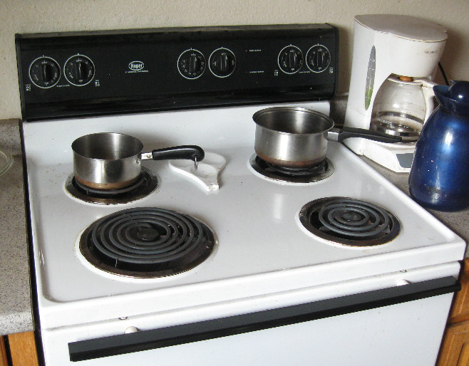
* I used a candy thermometer, which wipes pretty clean
when hot. Later (burner off and away from the stove) you can wipe the rest
of the pitch off with a little mineral spirits (paint thinner) and a paper
towel.
* My W-B pitch was pour-able at about 200 degrees,
so I stopped heating it at 230, stirred down the foam/bubbles, and took
it off the kitchen range at 205 degrees.
~ However, you
shouldn't need to take the temperature of your pitch, especially
when using the Gulgolz brand. Just slowly heat it to an easy pouring temperature.
** Again: go slow when adding heat and
do
not leave the stove unattended.
*** After many tests and reheatings, the bottom fell out
of one of my several Mason jars --which incident holds potential to become
a disaster. Since you don't have to experiment with a dozen different blends
and heat treatments of pitch like I did, skip the foil and jars. Just buy
a dedicated pan from your local Salvation Army store.
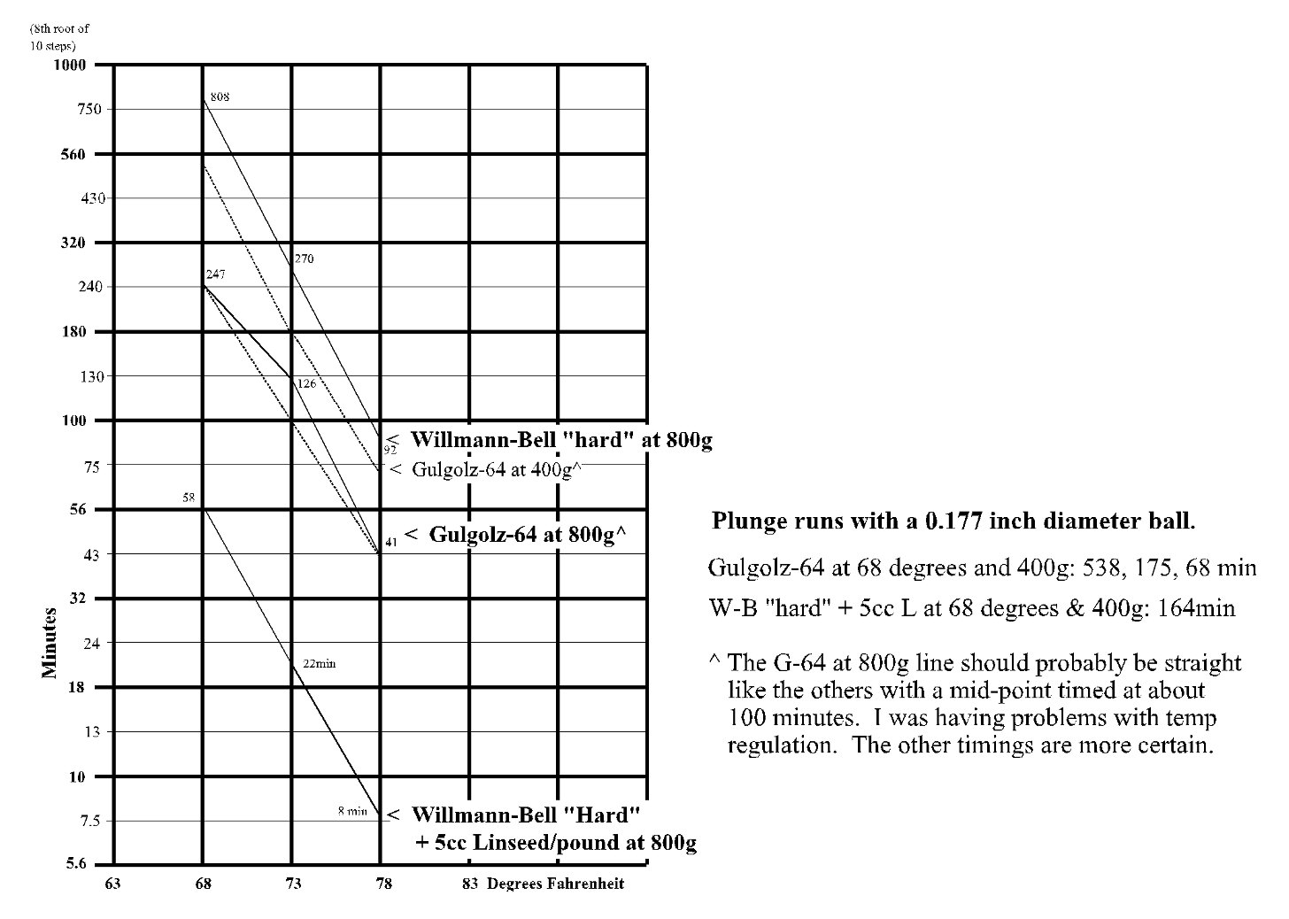
Hardness increases as temperature drops --and at a
steep rate.
The average of these rates is +22% per -degree F.
(click to enlarge)
* After much experimentation, I ended up with a batch
of pitch that plunge tested at 166 minutes (corrected to 68 degrees). I
can't tell you how I got to that hardness (too many detours and reheats),
but you can get there with W-B pitch by adding very little Linseed oil
(maybe 1cc per pound) --or: simply buy some Gulgolz-64 (which is said to
have conditioners against chipping) --which checks out at about the same
hardness.
The Pitch Lap
This is far from a complete overview of the pitch lap
and polishing --but it might hold few useful items.
* In view of the above graph,
simply raising the temperature in my (small) mirror shop let me do the
initial lap pressing ("cold pressing"^) in 3 hours. Another time it took
9 hours at about 70 degrees with the same pitch. I see no reason to do
"hot pressing" and risk mushrooming the lap tiles --or thermally imprinting
the mirror. (Those who make monolithic, poured and pressed laps must, of
course, do it hot --so hot as to almost be liquid.)
* I ended up making 7 laps for this one 6 inch mirror.
In the future, I'll only need to make the polishing lap once, plus maybe
a dedicated 12 micron grit lap.
* What really works well for adhering the pitch tiles
onto your ceramic (floor tile) grinding tool is to first wipe an almost
dry sheen of turpentine (the real stuff, not "mineral spirits") onto the
ceramic face.
~ Problem: wiping turps will erase
your lap lay-out lines, so deftly wipe/blot within the marked one inch
squares.)
~ I see no need to warm the tool
if the tiles are well candled. (Hold the squares by their opposite corners
--thumb and forefinger. Bring the rough side in close and somewhat under
the base of the candle flame, lest you be burning your fingers. Melt the
pitch just short of it running, then gently wring it down in place.)
~ For the 5th (a full sized) lap,
I tried to stick the pitch tiles onto residual pitch from the recently
removed 4th lap. That was a no-go. Every one of those tiles easily popped
off when tested.
~ It might be that turpentine only
works well for the pine tar based pitch that Willmann-Bell sells.
Pressing:
* I ended up pressing (using 10 pounds total weight,
including the weight of my 6" mirror --or about 6oz/square inch) with a
disk of synthetic window screen against the lap, and a single sheet disc
of (Reynolds brand) non-stick baker's parchment paper between the mirror
and the screen (to keep pitch from sticking to the glass). As the pitch
tiles comes into conformance with the mirror, that screen gave their shiny
surfaces a cerium oxide holding micro-faceted finish, so it's easy to tell
when pressing is sufficiently complete. (Baker's parchment also covers
the floor of my pitch strip mold.)
~ I think it's important to follow
screen pressing with 15 minutes (using 166m test pitch) of pressing with
just parchment (or tracing) paper, since the upwelling of the pitch flow
into the screen is surely irregular.
~ I do not like "direct" cold pressing,
using only cerium oxide or rouge slurry between. Such long contact has
transferred pitch deposits onto the mirror, which then become polish and
test fouling smears.
~ Again: I don't feel that initial
"hot pressing" is necessary for a traditional, discrete tiled lap. Extended
cold pressing works well for me (with 166m test pitch). One might raise
the polishing room temperature 5 degrees.
* Eventually, I ended up using a nominally full size
lap, but with a diminishing bevel --as is the normal practice.
* Mel Bartels
(no slouch!) holds the opinion that an over-sized lap prevents a TDE. (Truth
be known, Mel makes lots of great big mirrors, while I struggled mightily
with my one little piss-ass mirror.)
** The common wisdom is to ensure that the central
tile/square is well off center, so as to not polish in a pattern of zonal
departures, ripples or whatever into the mirror. So far I've been following
that advice, even though I suspect it's hogwash. What's more: I once managed
to "dog-biscuit" my mirror (meaning: mottling/choppiness) --anyway.
Mirror Testing
Although our optics goods suppliers, books and Web
resources bespeak surface departure errors in terms of a wave length of
light --implying that our criteria has to do with the heights of a mirror
profile (assuming that the mirror resting on its back), although
venerable authorities would have us graph out those profiles using the
very sensitive Foucault test, those heights are simply a convenient way
to reference mirror quality. It's actually the slopes which produce those
profile heights --it's the average slopes that we see in our tests --and
which confound our efforts to confine a star's image to a point at prime
focus.
These departures, seen at the radius of curvature,
are (of course) from what would be a spherical surface. When we do test
a spherical mirror, it looks perfect: no shadows in the Foucault test,
straight bars in the Ronchi test --which is often called a "null". What
we seek when "figuring" a well polished spherical mirror, however, is a
paraboloidal surface. Interpreting its departure from sphere in an easy
but precision way --is the essence of what follows.
The Ronchi Test
* Some parties in our ATM circles (most notably: Willmann-Bell)
count both the black lines of a Ronchi grating and the equal width
spaces between --such that a grating with 50 black lines per inch is said
to be a "100 line" grating. However, the vast majority of the optical and
science industry outside of our ATM community either counts only the black
lines --or: refers to the (black and white) "line pair" count of a grating
or a resolution target. Seldom do vendors, ATM web pages and other published
articles state which definition is being used.
* Most ATM workers who report and image or illustrate
Ronchi grating results place the grating just inside the focus. Fortunately,
most everyone is keen on stating whether a given Ronchi image or drawing
was inside or outside --because the results are opposite each other. However
--
Jerry Oltion
pointed out to me that a grating placed outside of focus gives a better
indication of the shape of the peripheral zone of a mirror, and he's right.
Once I tried outside-the-focus with a good Willmann-Bell grating, I converted
over from having been an "inside man".
* I can't think of an explanation as to why, but the
Ronchi image is also much sharper outside the focus, and that's with the
(W-B) grating turned to face either way. This phenomenon is much less apparent
when using a laser printed Ronchi grating. Presumably, that's because a
laser printed transparency grating is so crummy:
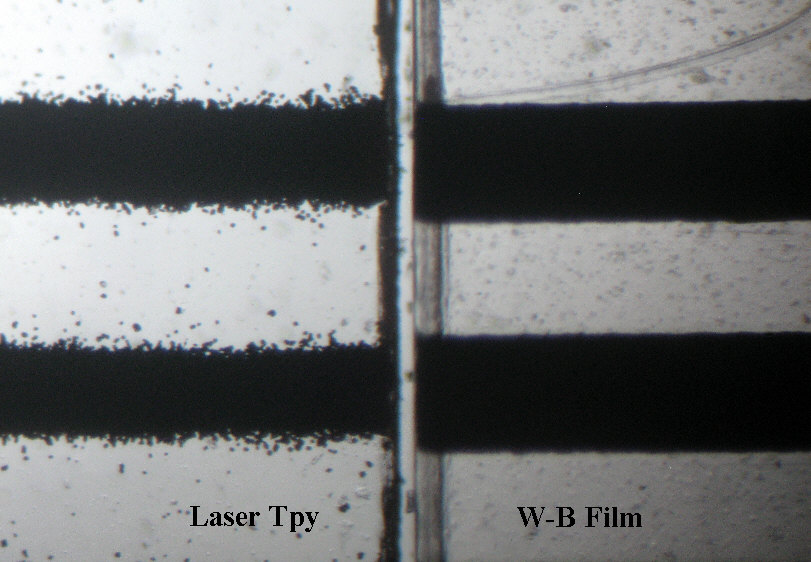
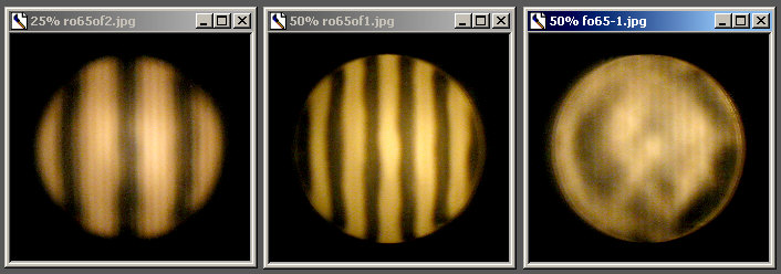
A comparison of two 50 line-pair per inch Ronchi gratings
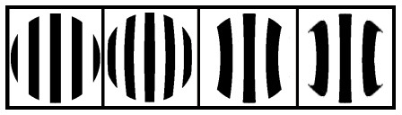
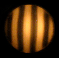
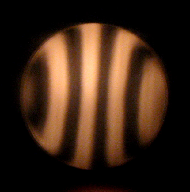
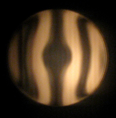
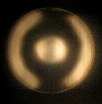
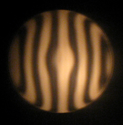
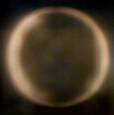
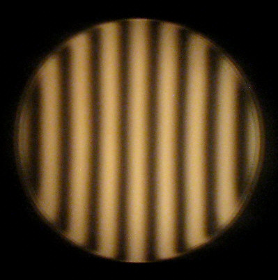
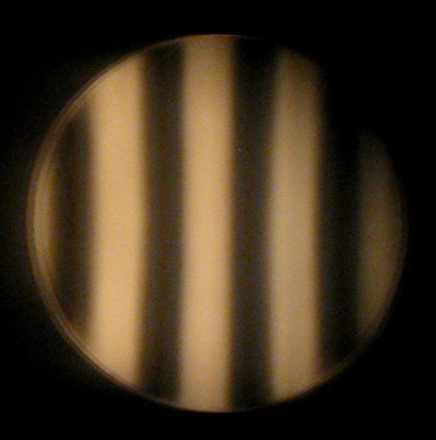
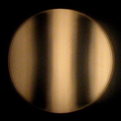
The basic Ronchi images: A - B -
C - D
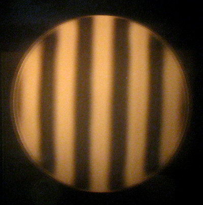
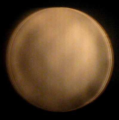
At left is what we see if the mirror has a nice spherical
surface, for which a Ronchi setup can be considered a fairly good "null
test". The following three Ronchi illustrations (all just outside of focus)
describe other surface shapes, which require seasoned, subjective judgment
to interpret: B: "oblate", meaning flatter (more shallow) than spherical;
C: deeper than spherical (might be paraboloid, might be "hyperboloid",
or too deep); D: deeper than spherical and the edge/periphery of
the mirror either remains sphere --or worse/flatter: the "turned down edge".
* A subtle variation on the above might be a central
area that's sphere, plus an outer/peripheral area that's either paraboloidal,
a different sphere, or oblate/TDE. In either case I go carefully (15 minutes
per session, minimum pressure, using rouge) with a long and wide (4/5ths)
"W stroke". This tends to over-run a TDE, but it also deepens the center^.
Should the center go too deep ("over-corrected"), I
resort to a 1/6th to 1/4th W stroke with medium pressure. That raises the
center --with less tendency toward a TDE than a 1/3rd W smoothing stroke,
but it also tends to make the surface choppy ("dog biscuit") --though not
as badly as does the short "I-stroke".
^ If you're making a small, long focus mirror (say:
f/9), you might be going for a spherical surface, or "figure", which brings
you within 1/8 wave when working a 6 inch mirror. (Presumably, shadowing
by the secondary lessens the effective error of a spherical mirror, but
not significantly for long focus scopes with minimal secondaries.)
More About Ronchi Testing
** Being such a lazy barsted, I've found that a (good)
Ronchi grating can be used like a Foucault knife edge (as others have noticed).
I've also skated out on having to add a micrometer pusher or a manipulator
to delicately move the grating left and right. I do lots of nudging, although
it's possible to move the Ronchi bars and adjust the focus point without
touching the Ronchi apparatus --by introducing and twisting glass slides.
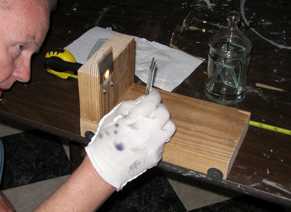
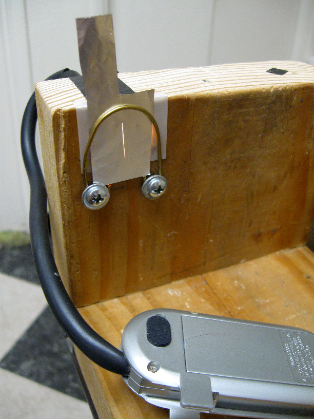
(click to enlarge)
This Ronchi apparatus simply slides along the edge
of a typical long folding table.
Illumination is from an AAA battery pen light shining
through a piece of vellum, and
then a good Willmann-Bell "100 line" (counts 50 line
pairs, actually) grating.
I'm holding a pair of microscope slides (home made,
chamfered edge, 1" x 3.5" window glass). The slides don't have to be optically
flat. (Any introduced problem would be readily apparent, of course).
By placing slides into the beams, the focus point of
the RC (radius of curvature) is lengthened. By checking a stack of slides,
I found that a single piece of 0.110 inch thick, "single strength" window
glass placed in both beams lengthens the focus by 0.035 inch, and by 0.0175
inch in just the return beam. A real (0.050" thick) microscope slide should
lengthen the focus by 0.016", a 0.025" thick cover slip by 0.008". (I've
since made a little slide-around wooden caddy for holding my glass slides
upright.)
If the mirror is on the paraboloidal^ side (its center
having a shorter radius of curvature focus), then use (say) 2 or 3 slides
for a long focus mirror and nudge the Ronchi apparatus to evenly darken
an outer donut area of the mirror first. Next, find out how many slides
to remove in order to darken the center of the donut --and to stop the
apparent Ronchi bars there from moving in the opposite direction when you
budge the apparatus (always moving in from outside the focus).
* I've repeatedly tried using "Couder"^ type masks
and variations on the simpler center-and-periphery masks we see in the
ATM-1 book^, but I feel much more aware of what's going on without masks.
As ATM-1 counsels, we're simply looking at the over-all difference in radius
of curvature, center to edge. That, together with seeing and knowing that
the surface smoothly transits from center to edge --is enough information
for completion.
(^See section II-31 of Texereau's book: "How To Make
A Telescope", pages 94-98 and 220 of ATM-1.)
When such measurements are made by way of using masks
and a Foucault knife edge on (say) a 6 inch mirror, the outer 1/2 inch
is looked at, and maybe a central diameter of 1.5 inches. The simple formula:
difference = r2/RC, gives us a good idea of where we're at,
mirror figure-wise. However: that formula applies to the focus difference
from the dead center to the very edge, versus the actual mean radius we're
looking at somewhat inward from the edge, and somewhat outward from the
center --since we need a goodly area for judging the shadows. Consequently,
"r" might be better taken as 2.5 inches, rather than 3, especially if the
outer edge has a strong bevel, or some TDE is to be abandoned. That would
yield 6.25/102" = 0.061".
~ The inner (say) 1.5 inches of
mirror (ie: a 3/4" radius) only accounts for .563/102 = 0.0055" of the
would-be difference, whereas the jump from r = 2.5 to r = 3 extends the
RC from 0.061" to 0.088" --something worth paying attention to.
~ Using my old eyes (and mind),
and not using a mask, it takes me a while to get grounded as to what I'm
looking and nudging at. I'm watching no less than a central 2 inches of
blob-like diameter (there goes 0.010") and maybe as little as 2.25 inches
of radius for the average "donut" diameter --for a perceived difference
of (maybe) only 0.039". For my (nominally) 6" x f/8.4 mirror (which would
probably work okay even if left spherical), I decided that just one glass
slide's worth of parabolizing difference was going to be just fine.
^ If your mirror is on the "oblate spheroid" side,
you don't need to know by how much. Just fix it.
* In order to tweak a single Ronchi line across your
mirror --or just the inner or the outer zone of your mirror, that can be
done by twisting the slides in the beam a little. However, I find it easier
to just nudge the apparatus or table a little. Sometimes shifting my weight
on the floor will do the adjustment.
* I mark a big fat arrow on the back of my mirror so
that it's always oriented the same for tests. Again: I always come into
the RC focus from outside the focus. The bars are cleaner and I'm better
oriented that way.
~ Be sure to turn off any heaters
in the room, lower the lights, banish your enthusiastic dog and your clumpity-clomp
restless spouse to a distant room, because your home is now made of quivering
Jell-O.
~ Famously: you can fairly determine whether
your mirror is sphere: the Ronchi lines are straight across.
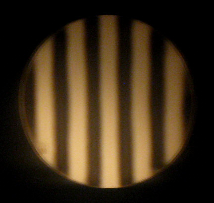
~ When it's deeper than sphere (possibly
a paraboloid): the lines curve to cup away from the center of the mirror
(when seen outside of the RC focus).
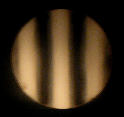
~ But: when the Ronchi lines curve a little
to cup the center of the mirror, it's --
slightly oblate
--but at least there's no sign of a TDE here
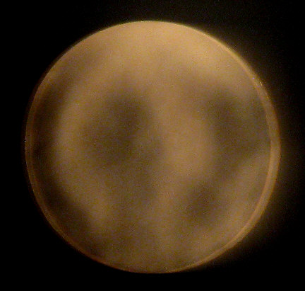
Not only is this mirror "over-corrected",
but it's got bad TDE as well.
(All of my Ronchigrams are outside of focus)
Is the mirror sufficiently polished
out?
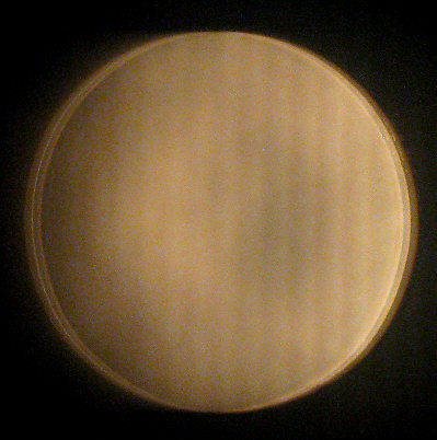
The Laser Test:
* Although any pits were long gone under microscopic
examination, I kept seeing the same, soft, granular light scatter when
giving the surface a laser light test --through 10 hours of polishing.
I switched to using rouge for the final hours of polishing and figuring,
but that made no difference. Perhaps this is just the nature of Pyrex.
A big tip from Jerry
Oltion is to illuminate the surface from just under the mirror's edge
--which eliminates lighting up surface dust --and which might more selectively
illuminate any actual pits. (I've not tried this yet.)
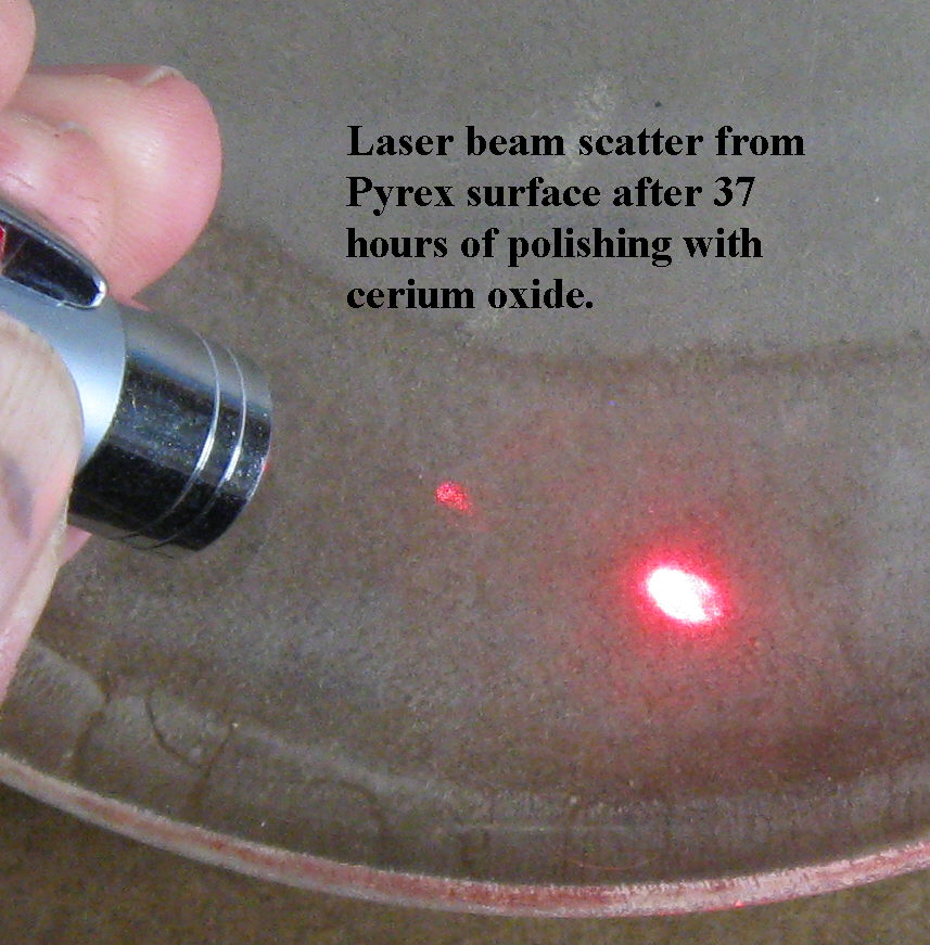
It looked the same at 76 hours, so maybe Pyrex always
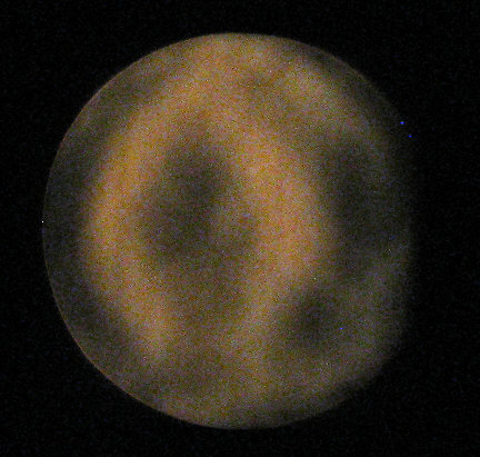
shows some sort of surface "grain"?
The brighter spot and that scabby looking stuff is
due to the casting impression on the back (far)
side of the mirror. Next time I'll first grind and
flash polish the back, since it's nice to have a clear
view of the grinding and polishing action (MOT). (Click
to enlarge.)
* At 40 hours, I was still fending off the TDE and
trying to coax a paraboloid out of the recurring sphere. What finally answered
was the classical parabolizing stroke.
The Jerry Test:
Jerry Oltion
recently discovered an excellent way to inspect for pits --which I look
forward to trying. Having previously smoothed and visually polished the
back of your mirror (well enough to observe your progress while grinding
and polishing), turn your cleaned mirror over --face down on a black mat
surface. Shine a bright light into the edge of the mirror, close to the
face. This method makes the remaining pits stand out sharply, but not any
dust stuck to the mirror's face.
The Star Test
Just as the single "blinking" line Ronchi test, which
is about the same as a Foucault test (which Jerry Oltion calls the "red
blood cell test" --which it resembles) --seems far and away more sensitive
than just looking at Ronchi grating lines, the "star test" is (reportedly)
yet again an order more sensitive. The basic idea is that you need your
telescope in good alignment/collimation and you need to do this test on
a night with good and steady "seeing", such that you can compare a bright
star's highly magnified image to either side of prime focus. Mel Bartels
tells us all about it at:
> www.bbastrodesigns.com/joyofmirrormaking/startesting.html#rigs
--from which page I call your attention to Mel saying:
"--you must learn the star test on small long focus mirrors. This is
the only way to learn the subtleties of the star test. Small long focus
mirrors tend to have fewer confounding defects, are more easily mounted,
tend to be less affected by cooling night air, and [by allowing the
use of less powerful eyepieces] keeps the eye's afflictions out of the
picture. Scopes with 4 to 10 inches aperture and a focal ratio of f/6 to
f/10 are best [to learn with]." With that statement, and with the striking
similarity of Mel's and Jerry Oltion's
star test rigs to a Dogson, I feel comfortable resting my case and advocacies
for
choosing a Dogson scope project.
* However, I find good seeing rather rare where I live
(near the Oregon coast) and the high power star test difficult to interpret.
Polaris seems too dim for my small mirror before it's aluminized, so I
picked out a bright star and manually tracked it. (I'm trying to remember
if I've ever seen a star here that wasn't somehow "boiling".)
* I've several times tried to set up an artificial
star --way up on a great sand dune which peaks about two blocks from our
front yard. However, my solar powered lights up there (clearly visible,
even at dusk) were short lived, thanks to bugs gathering in the dark and
kids gathering by day to tear them up. My impression was that for critical
testing, one must wait until the early morning hours --when the ground
is too cold to be sending up turbulent waves of warmed air. (That might
also be the best time to observe.)
* I tried it one more time with a convex mirror reflector
(that protectively bagged automotive accessory rear view mirror, glued
to the top of my stake, along with a yellow automotive reflector to help
find the stake at night):
 --using a 1/8th inch LED aimed off the front of my telescope
--which (I think) the -6 diopter convex mirror effectively reduced to about
0.0007 inch --plenty small, even at only 100 feet. (However: 100 feet is
rather close for null testing a paraboloidal mirror figure.)
--using a 1/8th inch LED aimed off the front of my telescope
--which (I think) the -6 diopter convex mirror effectively reduced to about
0.0007 inch --plenty small, even at only 100 feet. (However: 100 feet is
rather close for null testing a paraboloidal mirror figure.)
I had problems:
~ As mentioned at the top of this
page, the Dogson telescope design is a poor one for low altitude/terrestrial
observation. Although one can hoist the butt end up onto a high stool,
the balance and vibration gets bad. (Adding a purpose built stool would
help solve that problem, but I'm staying with the high astronomical aim
of my Dogson for now.)
~ The thin lens formula has served
me well over the years, but this time I didn't have as much back-focus
(closer subject/longer focus) as I should have. I did managed to squeak
out a 100 foot focus, however.
~ The faint diffraction disk I ended
up seeing was too dim to evaluate, so I'll just forget about testing a
non-aluminized 6 inch mirror this way.
~ The automotive mirror's surface
is simply not good enough. I saw smatterings of more than one point of
light.
~ Some while ago I made an artificial
star source out of a white LED for modeling small obstructed lenses at
50 feet or so --inside the house. Under a microscope its pinhole is quite
round and measures 15 microns (0.006 inch, but to subtend 1/4 arc-sec,
I'd have to place it 400 feet distant --and probably for checkered results
in the early morning hours. ---Hmmnnn
** So: unless someone can think of a much better way
to do it, I vote that star testing, artificial or real, is yet another
"hobby killer" which drains the sap, takes blocks of time away from the
goals of documented celestial observation, creative interpretation and
(at least) personal discovery.
I can see doing a star test at long last with a finished
and aluminized mirror --to document/log the mirror's true condition --should
one ever happen to have a night of great seeing, a high power eyepiece
handy, and a fully collimated 'scope at the same time --but not as yet
another hurdle to clear on your way to the observing chair.
* That leaves me with the fabulous "blinking"
test --aka: the cheap and easy, brighter alternative to Foucault testing,
by using a good Ronchi grating at focus.
* Standard Ronchi testing is,
of course, also very useful.
* The resolution target test:
Click on this image to get a full pixel count version
for your own use.
I printed this target one inch square, laminated it
with shipping tape and made it self-adhesive with double-stick carpet tape
--then stuck it high onto the post of a stop sign --about 330 feet distant
from our front porch. This is a traditional photographic standard for testing/proving
throughput resolution. If my mirrors can separate those bars at an arc-second
or better, what more could I want out of my optics? As it turned out, I
was able to distinguish the line pairs at only 0.81 arc-second --which
worked out to "32" (line pairs per inch) on the target --the diffraction
limit. Although line pairs are easier to see than close binaries or low
contrast planetary details, I can have confidence in this repeatable, "case
closed" test and I'm happy with the result. (Do this test in the early
morning hours, before sidewalks and pavement starts heating up.)
* The "hardware test": There's also the possibility
of using power pole hardware, but I found little by way of bolts with threads
or other repetitive shapes --save for transformer insulators. Those insulators
are too big for "neighborhood" use, but might be great if you have some
distant poles and transformers to examine.
* --And then there's the flattering,
feel-good, "Ronchi eyepiece" test, which is a paraboloidal null test (you
see straight lines). It's not very sensitive, but will reveal gross problems.
It consists of a 35mm film can with a hole in the cap's center --covered
with (say) a small piece of "150 line" (75 line pair) Ronchi grating. If
your mirror is at least a fair paraboloid, you see straight lines when
looking at the light of a star --spread out across your mirror. If that
star is other than Polaris, turn the Ronchi grating to align with the star's
drift to make the lines stand still. Otherwise, let the lines drift across
your image of the mirror and watch to see if they bend and wiggle --meaning
your telescope mirror is a can of worms :-) since this is not a very sensitive
test. (But perhaps it's sensitive enough.)
I'll be trying this test using a piece of positioning
film strip (150 LP/inch) from an old HP printer. and so will another member
of our e-group: Jerry Oltion (Astronomer's Workbench editor for Sky &
Telescope) --who has a much better observing location.
* Update: Jerry did so, carefully checking with 4 telescopes
--the mirrors of which he is very familiar with. Using 150 LP/inch is,
as expected, more sensitive (than half that line count) --perhaps good
enough to prove that a mirror is within 1/4 wave of true, but it's not
as prescriptively sensitive as a proper (in and out of focus), traditional
"star test". My own tests here, under a sky with rotten seeing, exhibited
straight lines across my 6 inch mirror, so two things: The Ronchi eyepiece
test seems to work when the seeing won't support a regular star test --and:
this test (like the others cited on this page) agree that I have a "good
enough" mirror.
A Grinding and Polishing Cradle
In trying to speed up the process of grinding and polishing,
I became persuaded that the rapid reversal of the mirror's direction (MOT),
when being normally pushed and pulled by gripping the mirror's top edges
--and especially when being moved by means of a traditional "handle", results
in a torque arm (against the inertia of the mirror's mass), which tends
to tip the mirror's leading edge down into the pitch lap --hypothetically
resulting in a TDE. Only after building a "cradle" to
minimize that effect, I found this problem well described on page #344,
and then about the same cradle idea on page #370 of Amateur Telescope Making,
Book #1, but manifested as the "steering wheel dingbat". It was invented
(circa 1930s?) by one J.V. McAdam.
** Although I no longer think that inertial tipping
is much of a factor, a cradle also keeps the heat of my fingers and palms
off the mirror, vastly improves my view of the lap at work, of my stroke
limits and of the periodic rotation of the marked mirror.
* Eventually, I realized that hand heat is very likely
a big factor in pitch hardness for small mirrors, and might well be why
so many 6 inch mirror efforts go south. Obviously, a proportionately larger
(say a) 10 inch mirror has 4.6 times as much mass to heat up, and 2.8 times
the radiation area to shed heat.
Those 3 top Teflon pads applied even downward pressure
on the mirror (or the option of no additional pressure) and the handles
provide alternative positions for old arthritic hands. Unseen is a pad
moderated thumb screw on the far side. Also: the right handle can be turned
to adjust the clearance of the right side bumper pad. The other two pads
are fixed.
Polishing station (click to enlarge)
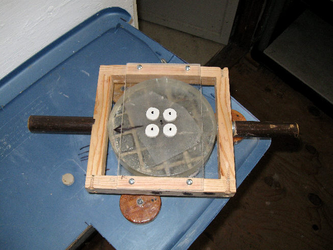
Here's a further development---
--in that the widely spaced Teflon pads in the upper view
have been replaced with 4 closely spaced felt pads --in hopes that centrally
concentrated downward pressure (as was the case when straight up stick
handles were used back in the 1930s) --would have less of a tendency to
produce a TDE. (That large, rectangularish patch on the mirror's back is
from the Pyrex blank's casting mold. It seems a good idea to fine grind
and coarsely polish the back of a blank before proceeding.)
Here we see 6 dabs of "office tacky clay" (buy the "Uhu"
brand), which really help to anchor the tool/lap. They work and release
best after getting a tad more dirty than what you see here. Note also my
tool turning index arrow and lap channel alignment lines.
Aside from being spoiled by the cradle's advantages,
I've come to realize how different are my efforts with a polishing cradle,
compared to the hands-on work we read about in our literature and ATM Web
sites. When using such a cradle:
* The mirror is significantly and uniformly colder,
with little or no temperature gradient, mirror back to face. How much the
mirror's temperature gets raised by hands-on polishing is, of course, an
individualized and variable factor that makes advice between workers iffy.
* The lap tiles also run at a significantly lower temperature
(8 degrees lower for me^) --and pitch viscosity is very sensitive to temperature.
^** I borrowed our son-in-law's optical thermometer,
which I first checked out for accuracy and consistency with different materials
(including pitch), finding it to be a good instrument.
^* After 30 minutes of hand "W" (1 inch stroke) polishing
on a 5-1/8" lap --mediated only by surgical gloves for non-slip friction,
I measured (a black tape target on) the mirror back at 82 degrees, (a cerium
oxide slick on) the mirror face at 79 degrees, and the tile faces at 78
degrees. Room temperature was 70.2 degrees.
^* Earlier, after polishing a normal W stroke with
the cradle on a full size lap for 15 minutes, I measured no more than +/-
1 degree differences across the lap face (I was expecting a significant
center to edge difference), and those temps were within 2 degrees of room
temperature. Even with a bit of demon polishing, the difference between
a tile in good contact and one in poor contact was about one degree. (I
had to work quickly to get near instantaneous readings, but I also did
second and third readings after waiting 30 and then 90 seconds for any
deeper tile heat to reach the facet faces.)
* I've read, and it seems intuitive, that there will
always be a bit of TDE --that the simplest cure is to mask it off --maybe
with flat black paint, but I'd use an O-ring.
* My cradle polishing did not go well. Mel suggested
I go to softer pitch and Jerry suggested going to mini or micro facets
--which effectively makes the pitch softer (aside from avoiding possible
stroke length resonance issues). I ended up doing both, but first I changed
just the best candidate: pitch hardness --and in view of the fact that
my polishing lap and mirror temperatures remain near ambient. I made another,
standard, one inch square tiled lap with softer (166 minute plunge test)
pitch --and got much better results.
6 inch mirror project notes section
At the 59th Hour (9/15/2015):
Ah do declare: neber did see such a hellatious "hill"
--!-- over half an inch longer in radius of curvature.
The left Ronchigram is at the hill's RC. The middle
image is at the surrounding area's RC.
At right is a general outside Ronchigram. (Wow: looky
dat turned down edge --!)
(Note how one can measure differences in zonal RCs
with Ronchi bars.)
* After seeing that hill, I took notice of a crack
across the central most lap tile. It must have settled lower than the others
(pushed further down by the "bakers parchment paper" I use) --and I failed
to notice the lack of polishing action there. Next I pressed at length
to equalize the tiles --plus I raised the shop temperature to 70+ degrees,
which made my (then) 418 minute test pitch nearly as soft as Gulgolz-64
247 minute pitch.
* ATM mirror work is not yet a science, it refuses
to be so constrained (at least for me), the advice we get is all over the
map --and "the map is not the territory" (Alfred Korzybski).
11/03/2015: Having gone to softer pitch (166 minute
test), I used short (1/6th to 1/4th) "W" stroking to address the TDE. That
"raised" the center, and while it reliably brought a slightly slightly
flatter curve outward from middle to edge with harder pitch (to either
match or to over-run a TDE), the advance of that corrective curve stalled
out with the new 166 minute pitch.
9/24/2015:
At 65 hours of polishing (my Ronchis are outside
of focus)
The right image was made by "blinking" with a Willmann-Bell
50 line pair ("100 line") grating.
It was back to using the 1/3rd "W" stroke for smoothing.
Then I had to use an all-out, classical, 4/5 (or so) "parabolizing W stroke"
to get even a hint of producing a parabolic curve. A pleasant and unexpected
benefit of this stroke was that it appeared to keep a TDE at bay.
At 72+ hours:
At 72.5 hours of polishing (my Ronchis are outside
of RC focus)
The right image was made by "blinking" the mirror
at focus with a 50 line pair grating.
Here's a dark and grainy actual Foucault-gram (made
with a 30 to 40 micron vertical slit)--
--which confirms that the lumpiness we see in my Ronchi
"blink-o-gram" is real.
My mirror seemed to be getting smoother, but I was
concerned about over-correcting --by continuing with a 4/5th "W" stroke,
1 minute rotations, minimum pressure, and red rouge. -----Hmnnnnn
Again: my polishing was not going well. Mel suggested
I go to softer pitch and Jerry suggested going to mini or micro facets
--which effectively makes the pitch softer (aside from avoiding possible
stroke length resonance issues). I ended up doing both, adjusting the pitch
hardness first. The new, standard, one inch square tiled lap with softer
pitch gave much better results. By impressing micro-facets with window
screen, I got much better "drag".
* Here's a cheap and sleazy-easy way
to (needlessly, as it turned out) convert your Ronchi tester to do the
slit Foucault test:
That's a book reading flashlight with a goose-neck.
Simply use a razor knife to cut the slit and the "knife"
edge
against the same straight-edge position (with
smooth plastic
for backing). I got about a 35 micron slit on the
first try.
Work in from outside the focus, so as to nudge the
return image into the knife edge,
rather than trying to chase after it when inside the
RC focus. You can also get numbers.

Comments on my 6 inch mirror at 74 hours (images 1,
2, 3, 4)
* Since the Ronchigrams at left are outside of the
RC focus, the mirror, overall, is slightly "oblate".
* My short "W" stroking nearly eliminated the 1/4 inch
or so of "turned down edge" I'd been looking at for days --presumably,
by
adjusting the rest of the mirror to match. Perhaps you can see a vestige
of it by clicking on and enlarging the first image.
* While that slight kink near the ends of the Ronchi
lines might escape casual notice, the reason for it is clearly shown in
the 3rd image, when the Ronchi grating is nudged into position to act like
a bright Foucault test.
* I find this 3rd image difficult to visualize. My
mind's eye wants to imagine a light source to the left. However: once you
"get it" with imagined light from the right, it snaps in and that central
area becomes a "hill" --a big smooth hill, sitting in the middle of a spherical
looking dish.
* It's not an actual hill, of course, but an ever-so-slightly
flatter central area with a slightly longer (radius of curvature) focus.
In the 4th image, the Ronchi apparatus has been gently nudged a wee-bitty
further from the mirror in order to find that longer focus --and Lo: it
"blinked", indicating that it was fairly spherical. (The surrounding area
could be blinked as well, at a slightly shorter focus.)
**At 75.5 hours: At
74 hours I'd proceeded on the gnotion that my (MOT) 1/6th to 1/4th "W"
stroking was slowly marching a flatter spherical curve outward, to over-run
the existing, peripheral spherical curve --taking out any vestigial TDE
in the process.
Nope, it didn't happen. The "hill" area got weaker,
then stronger --but it stayed put. I next used a 1/3rd W stroke --which
once got rid of a choppy surface and produced a nice smooth sphere (but
left some TDE). This time I got a more pronounced hill (again: a central
shallow area, actually).
* My next step was to tear into that stubborn hill
with
a 4/5th W stroke (which always gets results) for a solid half hour, with
medium pressure, rouge, a cradle, and the new 166 minute pitch lap. Although
apprehensive that I'd end up with a badly over-corrected surface, all I
did was remove that pronounced "hill" and produce a perfectly spherical
surface (and just a tad of TDE).
~ Due (surely) to my polishing room
starting out colder than normal --plus my long strokes, a few flakes of
pitch snapped off and smeared up the mirror. It took 3 cleaning sessions
with lighter fluid to get it all off. This has happened before with harder
pitch. I'm glad to report that it doesn't seem to mess up the mirror's
figure.
** At 76 hours:
For the last session, my polishing room started out
cold (66 degrees), so this time I had at it with the 4/5 W stroke again
--but with the room warmed up, and for only 15 minutes per session --with
minimum pressure. The first session produced just a hint of deepening the
mirror's center. The second session's results follow:

Comments on my 6 inch mirror at 76 hours (images 1,
2, 3, 4, 5)
* I roughly measured a center to periphery RC difference
something like 0.035" for this 6" x 50.25" (f/8.38) mirror. I tried measuring
that difference again with masks, but ended up returning to rocking a Ronchi
"blinking" bar back and forth.
* The "star test": We had fair sky with stars (also
with cold, wet and dog poop). I ran the power as high as 196x on a bright
star (Cygnus Alpha/Deneb at mag-1.3), since Polaris seemed too dark for
my unsilvered 6" mirror --but golly: the same(?) mess to either side of
prime focus didn't tell me much.
Hopefully, this "blink tested" tip-of-the-hat to parabolizing
is gud-enuf for a 6" x f/8.4 telescope.
Aluminization: *
My astronomy circle of friends having made no objections to the current
shape of my mirror (what can be seen of it via my Ronchigrams), next up
was to choose a coater and have it aluminized.
* The next order of business was to religiously clean
up the mirror. As mentioned above, I ended up having to grind off crusted-on
cerium oxide from the beveled edge, using a carborundum stone. After thoroughly
washing away the grit from that, I washed the mirror 3 times with Fells-Naphtha
soap (using a stiff little brush on the back and sides, face resting on
a clean, soft, terry cloth towel) while wearing surgical gloves. Next I
washed it with alcohol, followed with a good rinse, a finish rinse with
distilled water, and blot the mirror dry with clean, soft cotton towels.
* The second issue: how best to pack and ship my precious
mirror? (Answer: ask the coating service how they want you to package and
ship it --so they don't blame-shed on you for any mishaps.)
The packaging not only has to cushion the mirror from
blows, but the cushioning/bracing must not rub against the front of the
mirror in transit --to or from the coating service.
* One solution --and what seems to be the generally
preferred solution, is to wrap and tape up the mirror tightly in packing
tissue (but maybe with a piece of a soft cotton dish towel or tee-shirt
next to the mirror?), such that if the mirror moves, the wrapping moves
with it --no mirror abrasion --then pack the wrapped mirror in styrofoam
or typical plastic cellular foam sheets --cut to fit. (See the instructions
on that at:
> www.spectrum-coatings.com/Telescope-Mirror-Packing.htm
(scroll down to their instruction photos)
and:
> www.opticwavelabs.com/products.php
(click on "Customer Education" in the drop-down menu).
In Texereau's book, he suggests using four wooden wedges,
against which rests the fragile edge of the mirror's face. Should the package
take a hard blow, that would magnify and concentrate its force upon the
part of the mirror most vulnerable to chipping. However, Texereau wrote
this before protective coatings were common, and a fresh coat of aluminum
takes weeks to skin over its own protective coating of aluminum oxide.
* Paul Zacharias, owner of "Spectrum Coatings" (at
the time: $50 for a standard coat with a silicon oxide overcoat), suggested
packaging similar to this:
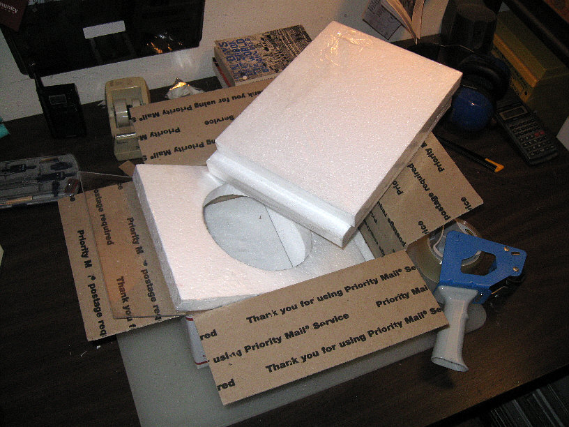 --but not in that USPS box. Both Spectrum and Optical
Wave Labs (OWL) prefer that I send it UPS Ground. The Spectrum web site
is silent about protecting and supporting the mirror's face, but when drawn
out, Paul also talks of tissue packing paper and such.
--but not in that USPS box. Both Spectrum and Optical
Wave Labs (OWL) prefer that I send it UPS Ground. The Spectrum web site
is silent about protecting and supporting the mirror's face, but when drawn
out, Paul also talks of tissue packing paper and such.
* That white stuff (from the UPS Store) is messy. Plastic
cells break off and blow around. Spectrum Coatings suggests using some
"blue or green foam from Home Depot or Lowe's", which must be available
from other building materials stores.
~ I asked Majestic
Optical Coatings for their suggestions as to shipping, packaging and costs
(none of which could I find at their web site --which might be due to my
fault/connections) and their Jeff Decker responded, suggesting that we
wrap the mirror in any suitable material (perhaps bubble wrap), snugly
pack it with more material into a smallish box, seal it, then pack that
box into a larger box --such that if there's to be any slipping and sliding,
it will be between the boxes and packing. (Jeff also assured me that their
coating process leaves no support or "fixture/rail" marks on the coated
surface.)
* Here's my mirror, back from OWL
--and it was less than a week for them to turn it around. The coating looks
perfect and that perforated center spot is accurately placed. Too bad about
the 3 support indents.
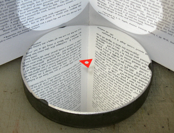
 By using a Stouffer gray step strip (something I needed
when I did commercial stereographics), one should be able to determine
the percentage of light being reflected, by sampling a photographic image
--with a simple graphics program --and comparing these density steps. They're
10 to the indicated power darker, where 0.3 equals twice as dark --or half
the the reflected light --or the photographer's "one stop down", and 0.15
equals a "half stop down", or about 70% of the light left.) It appears
that the mirror is losing something like "1/4 of a stop", which would be
84% of the light remaining. --Hmmnnn.
By using a Stouffer gray step strip (something I needed
when I did commercial stereographics), one should be able to determine
the percentage of light being reflected, by sampling a photographic image
--with a simple graphics program --and comparing these density steps. They're
10 to the indicated power darker, where 0.3 equals twice as dark --or half
the the reflected light --or the photographer's "one stop down", and 0.15
equals a "half stop down", or about 70% of the light left.) It appears
that the mirror is losing something like "1/4 of a stop", which would be
84% of the light remaining. --Hmmnnn.
The mirror was supported upside down in the coating
chamber by 3 round ears, which left those 3 bare spots, one of which intrudes
about 3/16 inch, so it's not fully covered by the 1/8" trim ring I'll be
using --per:
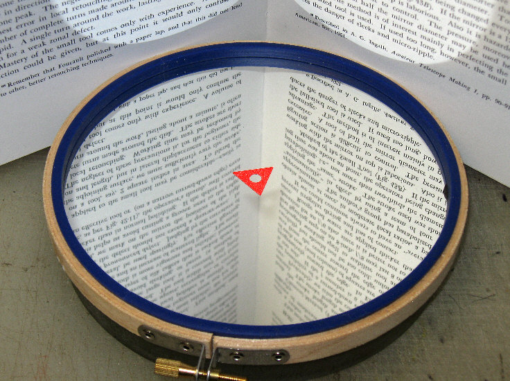 Oh well, I can easily live with that. (If this was a large
mirror, perhaps the support marks wouldn't reach past the beveled edge.)
Oh well, I can easily live with that. (If this was a large
mirror, perhaps the support marks wouldn't reach past the beveled edge.)
That blue thing is the trim ring --sort of a square
cross-section, 1/8th inch O-ring that I had laying around, which really
wants
to be a black, round cross-section, O-ring. It's cut a tad long, so as
to hold itself "roundly" in place. At 50.25 inches of focal length, my
Dogson then becomes an f/8.74.
What I ended up using for the collar
was a simple strip of black poster board paper, onto which I sprayed two
coats of artist's varnish. Then I Scotch taped it snugly to itself --such
that I could still pull it up to the height of the O-ring, at which point
I taped it to the bottom/edge of the mirror in 4 places. (I'll hang onto
that embroidery hoop for bench testing future 6 inch mirrors with trial
peripheral masks.)
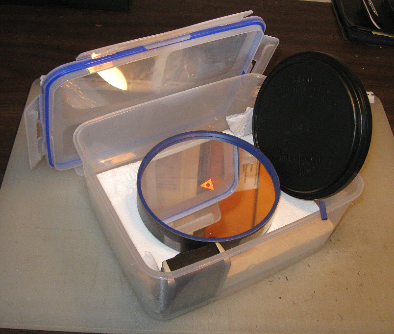 Here's the finished mirror in its
"SnapWare" brand, air-tight box, along with 2 baggies of desiccant and
an electronic hygrometer. The mirror already has a retainer
puck on its backside. The idea is to move the mirror into this box,
seal it, and store it cold (in our unheated carage/shop) --before the rest
of the telescope is brought into our warm house.
Here's the finished mirror in its
"SnapWare" brand, air-tight box, along with 2 baggies of desiccant and
an electronic hygrometer. The mirror already has a retainer
puck on its backside. The idea is to move the mirror into this box,
seal it, and store it cold (in our unheated carage/shop) --before the rest
of the telescope is brought into our warm house.
The trim ring's purposes are to cover the ragged beveled/champhered
edge, perhaps a wee bit of turned down edge (most mirrors have some), and
to present a smoothly defined aperture to the incoming light --per Gary
M. Bloom's web pages titled: "The Perfect Telescope" (which, unfortunately,
are no longer posted, but maybe you can find them via the "Way Back" web
site).
** Ohdear! The above storage idea
went bad. My telescope had gotten only a dozen trips outside over a period
of months --and just look at the crud on its face:
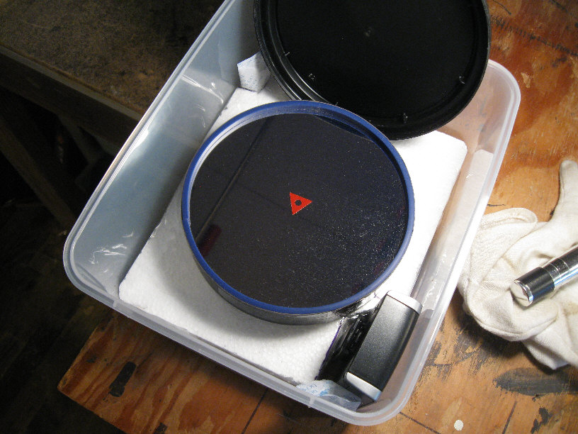
This is after air puffing and a camel's hair lens
brush --which
resulted in sleek streaks. (The whole mirror face
looks the same.)
I can only guess at what went wrong. Possibly, the
plastic box, that coffee can cover, or the inch of cellular plastic the
mirror's back is resting on --out-gassed platicisor. So here's what I did
next:
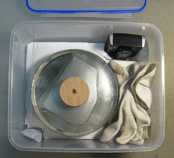
The mirror is now face down --resting on its trim
ring.
(That silvery area is a mirror casting blemish --which
I should have first ground and polished out.)
Beneath the mirror is an ironed flat, folded cotton
handkerchief and then the same one inch of cellular foam as before.
* Months later, it turned out that this arrangement
works fine. (To the right are a pair of cotton gloves at the ready.)
* My mirror cleaned up nicely, by the way, and I reactivated
the desiccant packets. (250 degrees F for 90 minutes.)
 2022 update:
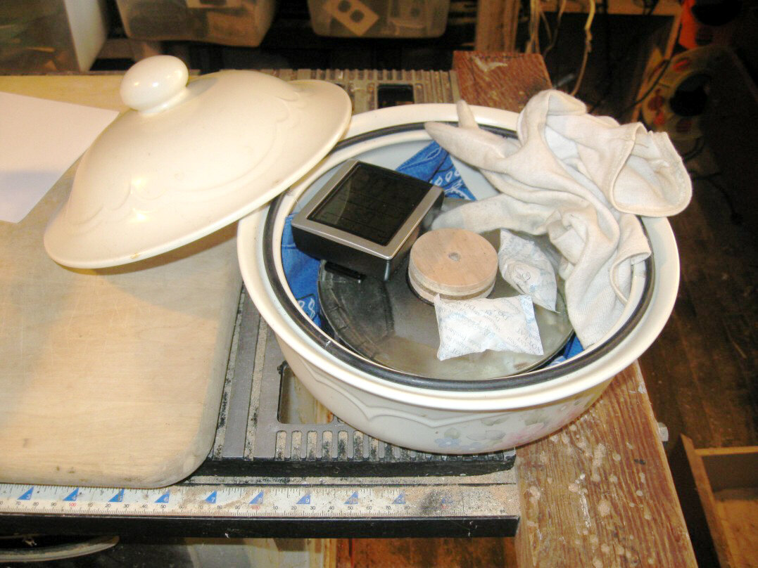
Here's what I should have done straight away --
--and thanks to prompting from e-friend Dave: use a glass
or ceramic container, plus some sort of a sealing ring. 25 inches of self-sticking,
3/8 x 3/16 inch weather stripping ("Frost King" brand vinyl foam) was perfect
for this casserole dish. Hopefully, it won't out-gas plasticizors --or
not as badly as did the old Snapware box. I'll keep storing the mirror
face down, of course. (The pictured O-ring seemed too stiff to make a good
seal.) Now all I need is some clear night sky.
Which coating to go for:
--the "standard" (88% to 90% efficient), "semi-enhanced"
(92% or so), or "fully enhanced" (95% to 96%). The cost difference isn't
much for small mirrors. What concerns me is that enhancements are achieved
by building up multiple layers: first the aluminum, then alternating layers
of transparent substances with sharply different refractive indexes (and
finally a protective overcoat --I presume). Getting the thickness and evenness
right for each layer is critical work, far more so than applying the basic
aluminum coating and one protective overcoat.
If done right, the diagonal shouldn't be coated alongside
the primary (as can be done with standard coating). Due to it being used
at a 45 degree angle, one would think the coatings need to be 70.7% as
thick.
~ There's an interesting article
discussing such considerations posted at Oldham Optical:
> http://www.oldhamoptical.com
(among several other subjects, like diagonal quality). It points out
that the Hubble Telescope mirror was not given enhanced coatings, and that
major observatories often use bare aluminum (which takes about 6 weeks
to skin over with a transparent layer of protective aluminum oxide). When
it comes time to chemically strip and recoat the mirror, a protective overcoat
(let alone a stack of undocumented enhanced coatings) might make the process
spotty and less predictable --perhaps even chewing up some of the glass
surface as well. (Thanks for these articles, Oldham Optical!)
~ I gather that nearly all coating
services routinely apply a protective overcoat, usually of silicon dioxide
or magnesium fluoride. Again: the overcoat presents no special thickness
problem.
~ The price for enhanced coatings
on a 24 inch mirror was recently (December, 2017) quoted at about $600.
At 25 inches, it (must be that it) takes "the big vacuum chamber", since
the price jumped to $1375. The regular price for a "standard coating" on
my 6 inch mirror (two years ago) was under $100 --which included return
shipping, packing and $10 extra for "center spotting" (applying a little
triangular target to help with collimation). If one is willing to wait
an extra week, OWL will also throw in a free precision mirror figure evaluation.
~ My practice with the Dogson (here
near the salty air coast) is to always take out the primary mirror at the
end of an observation session (it has a door and a single
thumbscrew for that purpose), then store it (face down) with desiccant
--for which its peripheral "trim ring" and collar worked out nicely. The
"SnapWare" brand 18 cup (size) sealable plastic storage keeper
is just right for my 6 inch mirror --and available in the kitchenware department
of a store near you.
The "finishing" touches
What (if any) optical tube assembly ("OTA") finishes^
should one apply?
* The inside, of course, has to be flat black (leaving
threads and bearing surfaces bare) --but what paint to use?
~ I don't like breathing the stuff
--or "over-spraying", so I went for a good bristle brush and a can of real
paint.
~ When I tap a spit wet finger on
the OTA's tempered HDF, it soaks right in --so I bought oil base flat black
(assuming it's better for oil/solvent to soak in, than the water of "latex"
paint --right?).
~ If you turn the rough side of
your HDF panels inward, that self-adhesive black "flocking material" (from
ScopeStuff) won't stick --but the rough side painted flat black seems pretty
good as is.
* Most everyone tells me that the best protective coating
is urethane spar varnish ("Helmsman" brand), and my HDF needed 3 coats
before it at least looked varnished. This way the outside of the
'scope looks like what it is: tempered HDF and wood. My inside and outside
coverage won't be 100%, but some should be better than none. (As soon as
I'd finished doing that, my 2nd oldest friend assured me that I should
have went with "Deft" exterior varnish, since a coat of that lasted 20
years on the propeller of his air boat.) (Oh well.)
In the next photo you see what I bought.
* I opened up the varnish, stirred (didn't seem to
need stirring), and poured it into a quart Mason jar --since I don't like
or trust resealing metal cans. Each time I decant, I wipe the jar's lip
and the lid/ring areas dry with a paper towel, so the lid will come off
easily next time.
* I decant an inch or so into another Mason jar for
use, the lip and lid of which also gets a good wipe when I'm done. While
that minimizes air exposure and prolongs the life of the varnish, my experience
is that varnish, once opened, will skin over in a few days anyway. Just
cut/pull it off and use what's left.
* That 3rd jar has an inch of mineral spirits for cleaning
the brush. First brush out as much varnish (or paint) as you can on one
of your crummy (and getting crummier) shop walls, clean some more with
a paper towel, lightly dip the brush in mineral spirits (don't swish or
stir --keep your spirits clean), brush it out some more, paper towel again
--and your brush is ready for another session.
* That white thing is chalk, for filling the many Phillips
head screw divots --so as not to fill them with varnish, but I've since
decided that a sharpened "Crayola" (brand) crayon works better.
* That ugly round thing in the OTA is where I plugged
a hole. (Some of my HDF was salvaged from another scope project.)

^ As you can probably tell, I know very little about
painting and otherwise "finishing" wood --except that you shouldn't apply
water base latex/acrylic type paints over oil base type paints and finishes
--and it also seems a bad idea over oil based primers or sealers. I have
my doubts as to whether paints, lacquers, varnishes and oils actually seal
wood/HDF, but I think they at least slow the ingress and egress of moisture.
* The collimation trip--
--is fairly simple for a long focus mirror. Whereas
with an f/4 telescope you have a 1.4mm diameter "sweet
spot" to center up (meaning: at best focus, coma doesn't detract from
a perfect mirror); an f/8's sweet spot is 11mm wide, and an f/10's
is a whopping 22mm.
I can do a fair collimation during construction without
the actual primary, by using a dummy 6 inch mirror --
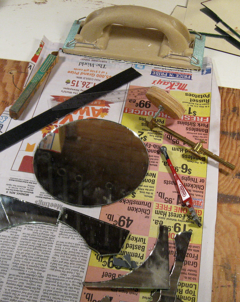 --made out of ordinary mirror glass by means of a circle
cutter. I center spotted and adjusted its location in Dogson-2:
--made out of ordinary mirror glass by means of a circle
cutter. I center spotted and adjusted its location in Dogson-2:
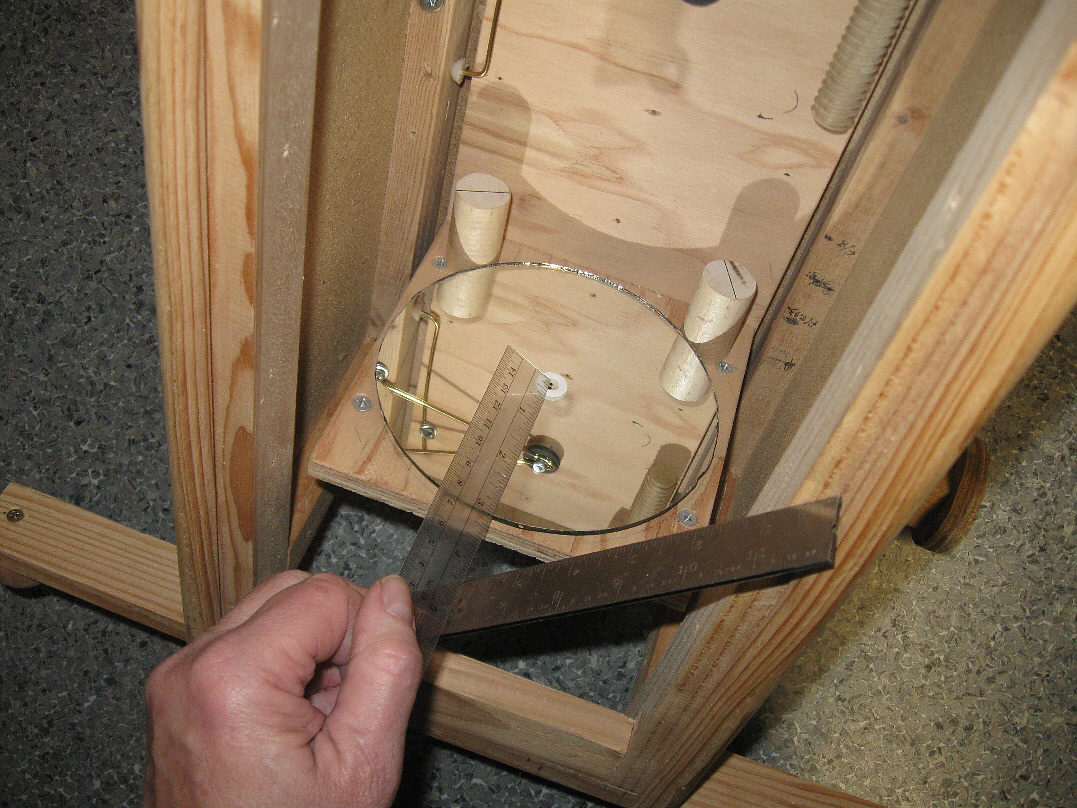
Those two edge supports are eccentric, such that the
mirror can be centered
by turning them. Since my Dogson is 8.5 inches square
on the inside, here
I'm measuring down 4.25 inches --from what will be
the bottom
of the top panel. (Photo shot before all the flat
black paint.)
Actually: that section of top panel is a door that
slides off for installing & removing the mirror, which is held captive
with a thumb screw. This seems a safest way to go
for the first approach to collimation, instead of putting the real primary
at risk of a dropped tool or fastener.
* I made a collimator eyepiece as well and it seems
to work:
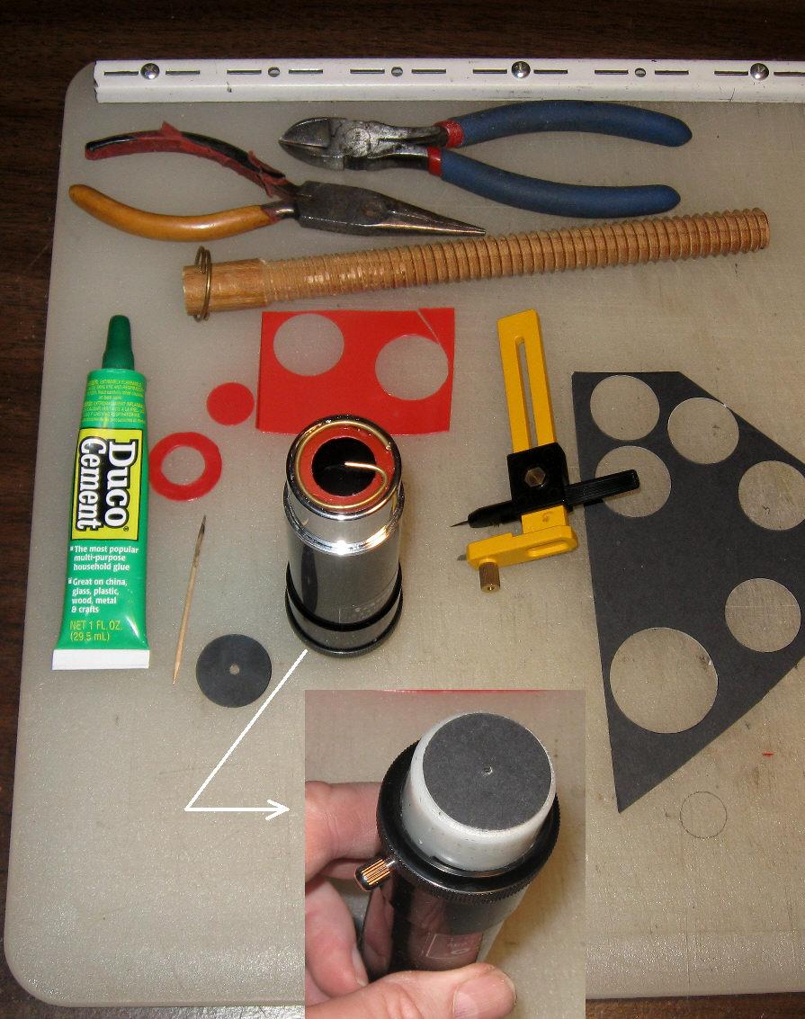
Using a junked out Barlow, I masked the field end
with red plastic--
to appear a bit wider than the diagonal. Instead of fussy
cross hairs, I glued in a brass "points-at". On the
eye end I glued on a black disk with a 1mm peep hole, which gives me enough
eyeball depth of field to sharply (enough) see the points-at and the field
mask. The other side of that peep hole is white and it's mounted on a translucent
35mm film canister --such that I can shine a flashlight and light up the
white side --something like a "Cheshire eyepiece". (Presumably, I'll want
to do that for some reason --right?) (*Click* my photos to enlarge them.)
~~~~~~~~~~~~~
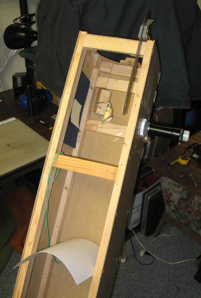
Collimation steps for the Dogson-2
(before I painted it flat black inside)
1) Center the (spotted dummy)
primary with a ruler, vertically and horizontally.
2) Verify that the ocular focuser is centered. (It
does focus a wee bit, due to the thread.)
3) Verify that the curved strut makes right angles.
and that the secondary mount dowel piece is drilled straight.
4) Center the strut's top end --vertically and horizontally,
with a ruler.
5) Install the collimator and make sure it's snug --no
slop.
6) Snug up all the adjustment screws, while still being
able to turn and position stuff.
7) While aiming and re-aiming the secondary
--so as to keep the collimator's center point on the primary's center spot,
introduce and remove (as necessary) the white poster board sheet and contrasting
color backgrounds behind the diagonal --in order to see and distinguish
the secondary (just the secondary) --and to concentrically center it within
the collimator's mask (custom made for this purpose).
Depending on how well you planned, cut out and drilled
out this scope, you might have to enlarge the strut base block's location
holes in the OTA bottom panel, then add fender washers to span the
holes (--like I did.)
8) That having been accomplished and the various screws
tightened down (without disturbing your collimation), it's time to adjust
the primary's 3 locating screws. (There are no "locking" screws nor mirror
retaining clips in the Dogson design, just 3 rather tight (nylon T-nutted)
thumb screws tipped with soft electronics solder.)
~ In the photo is a length of green
#10 or #12 gauge electrical wire. I use it to reach down and tug on the
(dummy) mirror a little bit to see which screw I want to turn which way.
This helps a lot.
When the reflected image of the diagonal is centered
up, you're almost done.
9) Finally install the actual primary mirror, bring
it to infinity focus, exchange the eyepiece for the collimator, and tweak
the primary's 3 locator screws as might be necessary.
For a more informed and universal guide to collimation,see
(and save) Don Peckman's page at:
> http://dbpeckham.com/Telescope/Collimation/Collimation.htm
Different strokes
The two-star strokes ('taint many!) seem most likely
to succeed):
* At first I hoped to discover a stroke pattern --or
a pattern of strokes, which would surely lead to a fair spherical figure
--as one would logically expect, and where the "proper application" of
the venerable "W stroke" is often said to lead.
* My fall-back goal was to assemble a small and simple
armory of strokes which, used one to mitigate the other, will definitely
and prescriptively produce the same result. (I've only selected, defined
and restricted these strokes --all of which have long been variously practiced
and advocated by others.)
* Unfortunately, my methods (unless found to be more
widely applicable by others) will probably have only limited application
--to the making of a traditional, shallow (f/8 or so), small mirror, from
a thick blank, by means of a "cradle" (at least in the polishing stages),
using a lap made of discrete tiles and the hardest pitch which is practical
to use (about the same as Gulgolz-64 at 68 degrees Fahrenheit) and keeping
the mirror on top ("MOT").
* Normal stroke speed:
~Slow: the mirror averages about
4 inches per second (varying sinusoidally)
~Normal: 8 inches per second
* Normal rotations:
~The mirror is turned 45 to 90
degrees CCW each minute (maybe more --to distribute slurry).
~My stance moves about 30 degrees
CCW around the tool at 5 minutes (avoiding
alignment with the
lap channels) through 150 degrees, completing 180 with my
return to the starting
position (that
drain mat work surface cut-out).
~ Each session (30 minutes) the tool/lap
is turned 90 degrees CW.
* One minute R&Rs (important for short and parabolizing
sessions):
~The mirror is turned 45 to 90
degrees CCW each minute.
~My stance moves about 30 degrees
CCW around the tool ALSO at 1 minute
intervals (avoiding
alignment with the lap channels) through 150 degrees,
completing 180 with my return
to the starting position.
* Stroking pressure, rudely defined:
~Minimal: only the weight of the
mirror and the cradle (about 3 pounds, 2 oz/squinch).
~Medium: the weight of hands and
forearms --5 pounds forward, 4 back (5oz/sqinch).
~Normal: Conscious pressure, which
adds about 5 pounds for me (7.5oz/squinch).
~Heavy: Adds another 5 pounds for
me (3 + 15 pounds (10 oz/squinch).
** The following strokes were mostly explored with
much harder pitch than what I've ended up using. I'm gradually revising
my comments here to reflect results with the current 166 minute (test)
pitch lap.
* A 1/6 to 1/4 "I stroke" (ie: straight, center over
center), applied with normal pressure:
~Rapidly eliminates a TDE with
hard pitch.
~Raises a central hill (even a
hill within a hill with hard pitch).
~Results in a very choppy surface
if prolonged (ragged Ronchi lines).
* A 1/3rd and greater "I stroke", applied with minimal
pressure and 1 minute R&Rs:
~Reduction of TDE and any central
hill is gradual.
~Tends to result in an oblate spheroid.
~Tends to leave the surface mildly
choppy.
* A 1/3 wide by 1/4 high "Tangential stroke", applied
with medium to normal pressure toward one side of the tool:
>This stroke is carried over the
edge until "pinch" resistance/drag is just felt (or just short of that).
>The mirror is rotated CCW every
60 seconds.
>One's stance is moved 30 degrees
CCW every minute.
>Tool/lap rotation is only needed
if stance rotation is less than 180 degrees.
~This significantly reduces a central
hill in about 15 minutes (Pyrex) --and
~Appears to reduce a TDE as well.
(With more rotations, Jerry reduces a TDE this way,
but with TOT.)
~Produces an ever more choppy surface,
though not nearly as bad as a short "I stroke".
* A near 1/2 wide by 1/3 high "Tangential W stroke",
applied with minimal or medium pressure:
>This stroke is also carried over
the edge until "pinch" resistance/drag is just felt, then returned
to center.
>The mirror is rotated CCW and
one's stance is moved 30 degrees CCW every minute.
>Tool/lap rotation is only needed
if stance rotation is less than 180 degrees.
~So far, this produces a spherical,
TDE-free figure with roughness if medium pressure is used.
I was hoping for smooth
results with minimal pressure, but the roughness persisted through an extra
hour of polishing. Also: the mirror remained slightly oblate, so I had
to aggressively attack the center of the mirror (which resulted in a rough
surface again).
** A 1/6 to 1/4 "W stroke", applied with medium (or
minimum) pressure and normal rotations (or one minute R&Rs for finish
and figuring stage):
~ Smoothes the mirror, with less
tendency toward a TDE.
~ Tends to produce a "hill" (a
flatter central spot with a longer RC).
** The standard, 1/3 "W stroke", applied with medium
pressure and normal rotations:
~ Smoothes a mirror, but with a
tendency for TDE to creep in.
~ I saw little reduction in the
radius of curvature during many hours of polishing out #500 pits^ with
this stroke.
~ Working with a cradle and a 166
minute (test) pitch lap, this stroke showed no tendency to remove a "hill",
once it was established with a long period of 1/6th to 1/4th W stroking
(used to get after a TDE).
** The classical, 4/5 (wide and
high), parabolizing W stroke --applied with medium
pressure. This is the only stroke (for me, and using the cradle) which
turns out a paraboloidal surface. My initial impression is that medium
pressure, and perhaps even minimal pressure --results in a small, but unacceptable
degree of surface roughness. There's posted talk on the Internet about
needing to actually lift off some of the mirror's weight (MOT) in order
to get the best results. I hope that's seldom necessary --it wasn't for
me, using Pyrex glass.
~ My most recent experience with
this stroke (30 minute session using rouge, a cradle, medium pressure and
166 minute pitch) was that it removed a pronounced "hill" (large, central
shallow area) and produced a perfectly spherical surface. My polishing
room was a tad cold, however, so will have at it again --warmed up.
^ Those #500 pits were deliberate --and the last fine
grinding stage, since scratches are most common during grinding with "micron
grits". Also: old timers didn't have micron grade grits, so I wanted to
see how tough it was to polish them out --and with Pyrex to boot.
(The remainder of this page is under edit. Find
some poorly organized Dogson-1 information mixed in.)
The Dogson Telescope
Some of the following appeared in the Fall 2008 Issue
#59 of Amateur Astronomy magazine.
(Last worked on: 6/3/2016, but lotsa older stuff here
yet.)
This telescope, without my knowing how it would end
up, went through design changes for 59 years --since I was 14 years old.
I think it's finally matured into a satisfactory 'scope. The only things
which haven't changed since my initial equatorial mount effort is that
it remains a long focus Newtonian instrument, embodied in a closed tube
(the "OTA"/optical tube assembly) --and a rectangular one these past 20-odd
years. The accompanying photos reveal extra holes and scars which attest
to mistakes, redesigns and modifications --in the Dogson's long struggle
to be born.
Now that the design has finally stabilized, best I'd
recognize/admit that this is only the second "roll-out" in 13 years --by
calling it the "DHS-2A1" (and, as ever: just "Dog-2").
The "DHS" part recognizes and appreciates Mr. Holcomb's
and Mr. Sellers' priority (see below).
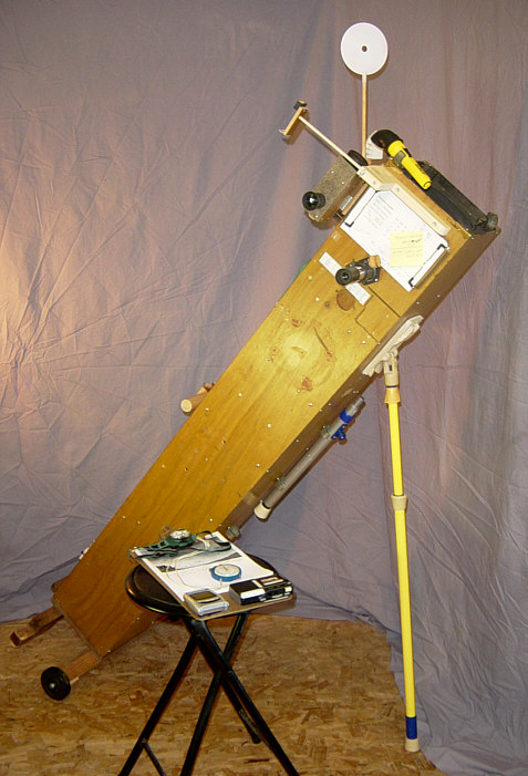
In my opinion (something which changes
with age), it's important that the doing of astronomy be physically comfortable,
not demanding of time or sleep, and not overly intrusive into one's family/personal
life. Whether it's simply "sky appreciation" or (as is my preference) some
sort of a personal project or thesis that you're pursuing --don't stand
when you can sit, don't observe at 4 AM when you can do it at midnight
on another date, don't guide photography for minutes if you can get adequate
results in seconds without tracking --or if you can conveniently whistle
up imaging from a robotic telescope --or if the astrophotography you need
already exists and is accessible, via the many Internet resources we now
have.
The most pleasant way to personally
take in the night sky is probably with a good pair of binoculars,
either while leaning back in a lounge chair (using a counter-balanced binocular
mount) or comfortably seated at a sturdy table (your short tripod mounted
binoculars fitted with angled oculars, your charts and etc. at hand). Next
best would be some kind of a (light concrete) table mounted telescope,
perhaps in the style of a Questar. 3rd best (hopefully) will be one of
my forthcoming "Dogson" telescopes --perhaps even a "Dogstar" version.
* In general, I suggest you'll
be happier looking at familiar objects (perhaps some variables that you
follow for the AAVSO) and using low to medium magnification --not much
more than 60 power, since that's about as much as average "seeing" supports
with excellent contrast, visual resolution, a nice field of view, a comfortable
exit pupil and eye relief.
For observing
with a telescope, one is tempted to go for a 45 degree "erecting prism",
such that sky charts, aiming and moving the scope are intuitive --rather
like a binoculars experience (but without the sore neck). We're cautioned
that such an "Amici" prism "won't work with DOBs and other Newtonians"
--for lack of enough inward focus travel, but that it should work with
most refractors and Cassegrain or Maksutov-Cassegrain telescopes.
A William Optics Amici prism
should also work with a Dogson-2 telescope, due to its traveling cell sled,
and provided it has an adequate secondary mirror. However, at this point
I only intend to use an Amici (if at all) for terrestrial observing, and
future Dogsons might forgo this option in favor of more focal length (f/8.66+).
(I've read that even the best Amici prism will add a horizontal spike to
bright stars.)
* I also suggest that you'll
be least happy when trying to do imaging (photography), unless you keep
your approach really simple and fast (like: a camera aimed at the sky and:
*click*). I'm really torn on that issue, since I do much better
actual "astronomy" by analyzing photos/astrographs --than I do in "real
time" at the eyepiece. (For more on that approach, see my (and others')
"barn door drive" experiences). Never-the-less, I fantasize
about doing direct astrometry, photometry
and sketches --in real time --at the eyepiece. (Ha!)
* In my humble opinion: if you
live in or near a city, a 6 inch f/8-10 (however configured) might be all
the telescope you want or need^, and something much smaller (like binoculars)
is what you'll likely use the most --provided that you're familiar with
and can navigate with your instrument, you know what objects/fields it
works well with, and you have a well configured observation setup/setting
--including a well behaved telescope or mounted binoculars,
a nice chair, an ample work table, notes, adequate illumination, warmth
and charts near to hand.
* Yes: "adequate illumination",
meaning white light --perhaps as a headband mounted LED lamp. Adequate
"red light" is no better than white at not knocking down dark adaptation
(IMO), and fuzzy "night vision" is only good for logging and bragging on
having noticed faint "DSOs". I want to study, count, measure and describe
stuff.
* The nebulas in Orion, of course,
are reason enough to purchase or build a larger 'scope. Our Coulter 13"
really did a job on that and other such objects, but I think you need reasonably
dark skies --and it is not fun (IMHO) to drive to some distant spot, set
up, fight sleep, and then drive home half dead (unless you go through the
greater inconvenience and grunge of turning it into a fursluginer camping
trip).
^ Most observers (especially
modern ATMs and ATBs) disagree with me, saying that bigger is always better
(aside from any portability and set up inconvenience). My opinion is influenced
by living very near the Pacific coast under an urban, often hazy/cloudy,
light polluted sky. I jointly own a good 13" reflector with my friend Chuck.
I've wheeled it out and tested full aperture, then with a 5" (oval off-center)
aperture mask, looking nearly straight up at something like M-13, --and
seeing little advantage in the full aperture.
I'm also biased in favor of the
people-compatible dimensions, weight and the relative simplicity of "eyeball"
collimation possible with a 6"x f/8 to f/9 instrument.
* So: many opinions here but no
"discoveries" to report (other than what's turned out to be film anomalies).
Like many observers, I've seen fascinating
apparitions among the Moon's fleeting shadows. Do take at least 15
minutes to steadily watch the Moon's terminator sweep along while the Sun's
grazing rays catch prominences --so stark and isolated on the terminator's
dark side that they look like colossal artifacts.
The scope shown
here is what's become of Dogson-1 --now in the hands of my friend Buddy,
who follows the stars under far better Oregon skies than we have here on
the coast --and he's already improved upon how I'd configured that scope
--
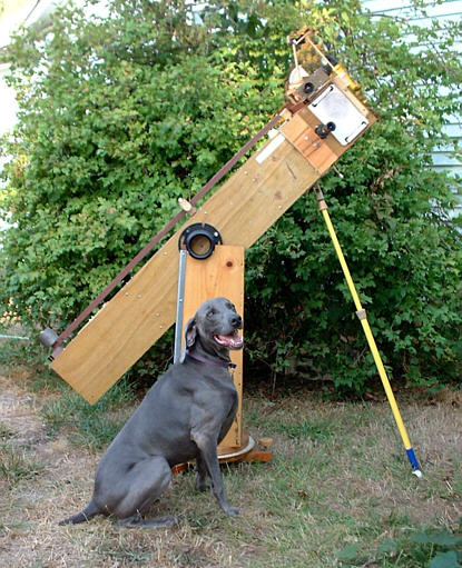 --by turning it into a "Buddsonian".
Buddy's loyal dog "Shadow" is demonstrating the design's stability. It
uses a high rocker box plus the foreleg that you see in the early part
of my Dogson article: the best of both designs!
--by turning it into a "Buddsonian".
Buddy's loyal dog "Shadow" is demonstrating the design's stability. It
uses a high rocker box plus the foreleg that you see in the early part
of my Dogson article: the best of both designs!
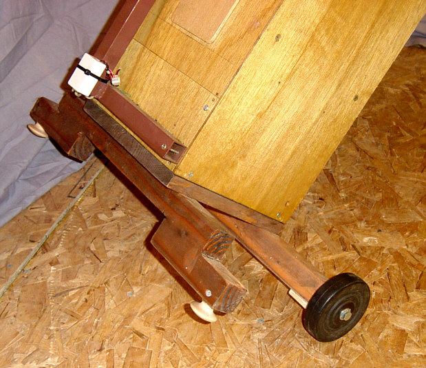
Dog-1's wheels, which don't turn, get relieved by
the pads of that upper arm at high altitudes --just
before
the scope's center of gravity goes over center.
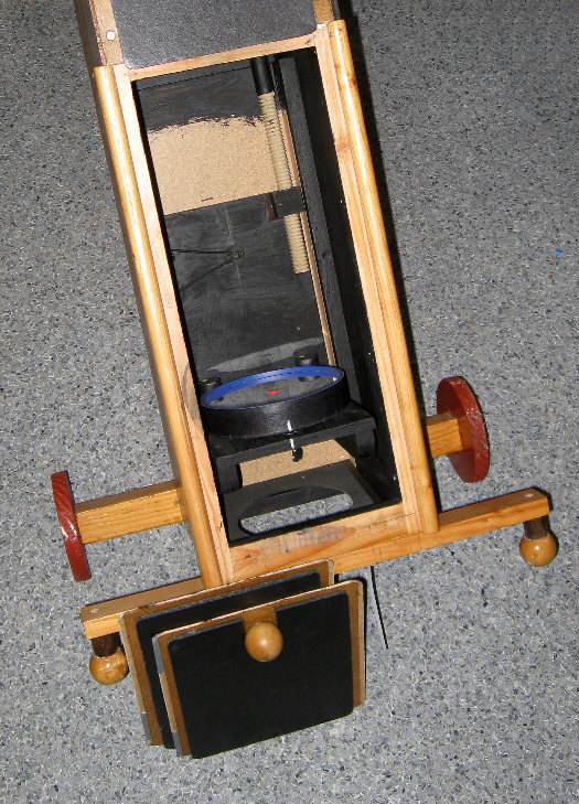
Dog-2 (seen here before the last of the flat black
paint) ended up with 5 inch
wheels and 1 inch extended over-center balls for better
rough ground clearance.
However it was to come out, I wanted my telescope to
be simple, stable, humbly practical, and easy for others to build, but
perhaps it's mainly "easy" in that one doesn't have to worry about weight
distribution.
I'd been inspired by the obvious
stability of F. J. Sellers' 1920s design, which our regional discussion
and construction group: "The Toledo Scope Works", took a look at some time
ago. (David, Chuck, Jerry, Tom, and Ted of the Scope Works were the reason
and the resources by which I was able to resume my old passion for astronomy
and telescope making. They've been supplying me with ideas, software, encouragement,
and components for years. David made the mirror and Chuck made the Crayford
focuser for Dogson-1. I've yet another 6" mirror on hand from Jerry --"Dog-3"?)
** A newer fellow at the Skope Works, Mel Bartels (who
goes way way back with the Oregon ATM scene, plus he has a great presence
among our literature and web sites --including his own) --alerted me that
this type of mounting goes back much further than Sellers. It was invented
by the first manufacturer of telescopes in the United States: Amasa Holcomb,
who you can read about at:
> http://www.bbastrodesigns.com/HolcombeMount.html
> http://labbey.com/Articles/Mason/Largest.html
> http://en.wikipedia.org/wiki/Amasa_Holcomb
Holcomb was a self-taught American Renaissance man
who lived a long life and made great use of his time. He started making
telescopes later in life, purely for the love of doing so, but ended up
filling many orders from private and institutional clients. There are a
number of observatories which still bear his name.
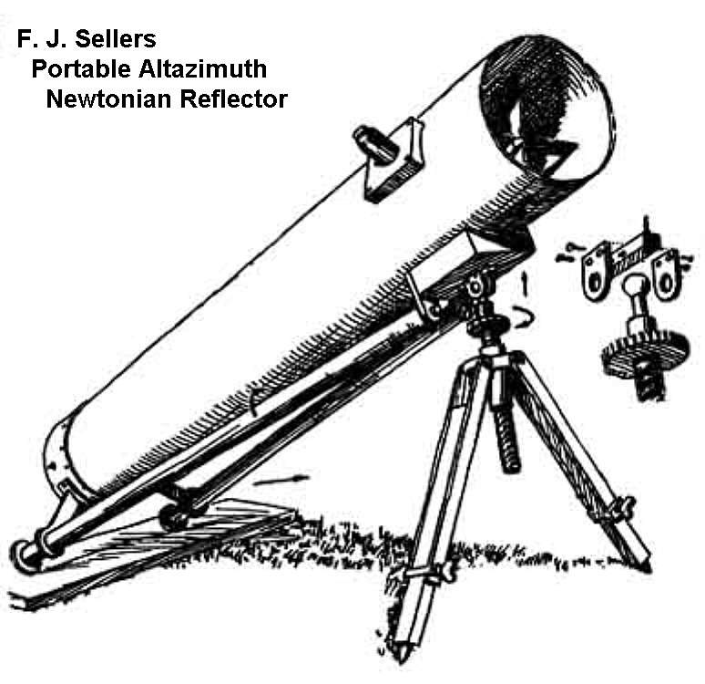
Sellers, a professional astronomer, considered alt-az
mounts superior to equatorial for visual use. He discarded
several designs before settling on this one. (Yes:
he carried
along that little board in back for smooth azimuth
guidance.)
My 'scope became a "Dogson" (with a humble tip of the
hat to John Dobson's fine telescopes, spirituality and philosophies) after
I started trying to figure out how to add a foreleg or two:
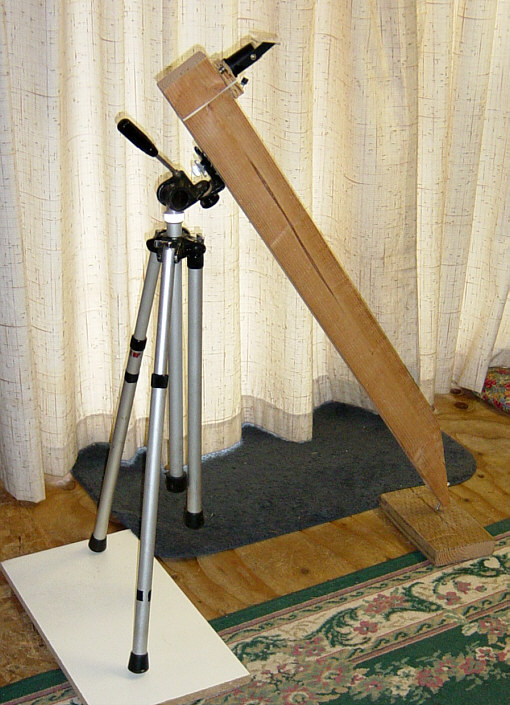
(04) Modeling design variants and trying
to get a "feel" for how it would handle.
To make a long trial and error story short, my first
Dogson ended up looking like this:
That flimsy stool is only for holding my clipboard
and whatever's attached: stop watch, a good clock,
microsette recorder and a headband light for seeing
stuff at night. My poses were to stand, stoop,
or go down
on a knee. The short leg was used under 30 degrees
of altitude
(ie: not often). Those rubber cane tips come off to
be replaced by --
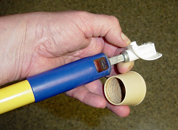
--a cut down plastic caster which swivels to catch
the dirt and allows the pole to be smoothly turned.
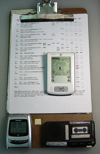
I need a lot of light to see its little display, but
this affordable --
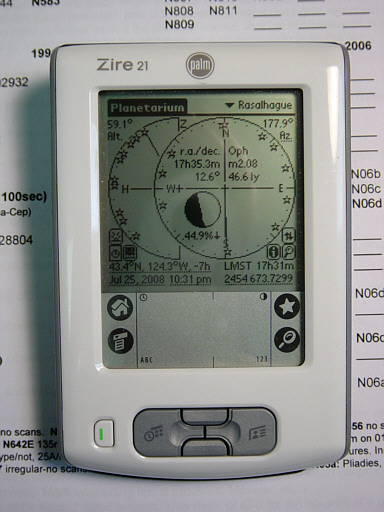
--Zire 21 and the Planetarium program supply the information
I need
to aim my scope. Each of those stars was at
the center of one of my
"Observation Areas" --which I watched and photographed
for years
in hopes of at least getting to know a few small parts
of the sky.
The Dogsonian design eliminates bearings, counterweights,
weight and thinking^.
^Well, some. It takes a bit of thinking to relate sky
program or planisphere co-ordinates to one's plan for the evening and night.
What I'm trying to say is that it takes a lot less thinking to turn out
a Dogson --a 'scope which doesn't need balancing, and which has cell sled
focusing with a good range of adjustment. It's easier for an amateur astronomer
to build and to transport this one-piece design (plus kneeling pad, which
stows on top of Dog-1).
Yes: that's an ordinary hardware
store or paint shop "pole sander block" and extension tube (30 to 60 inch)
--which attaches with an Acme thread --which, when turned, gives slow-mo
on the altitude. Dogson-2 uses a much longer thread, but operates the same
way.
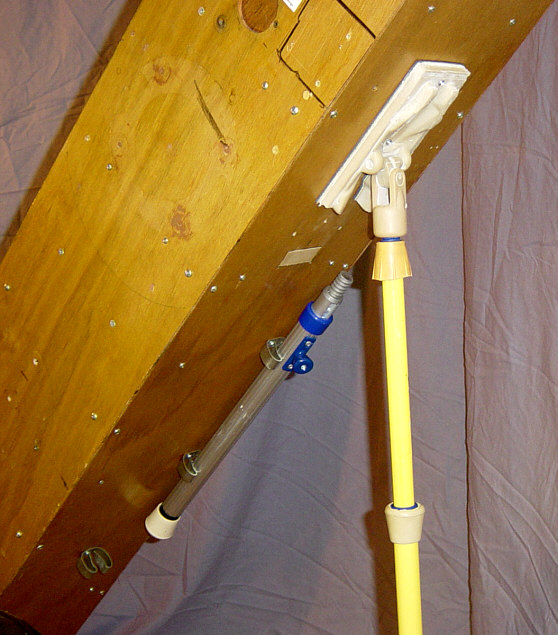
There are cheap through professional extension poles
to choose from. That aluminum pole was easy to
cut down and it adjusts in steps. Dog-2 uses a custom
made pole--
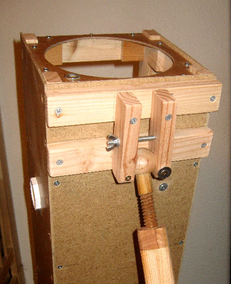
--and adds limits to the pole's
lateral
excursions, such that the 'scope can't easily fall
over.
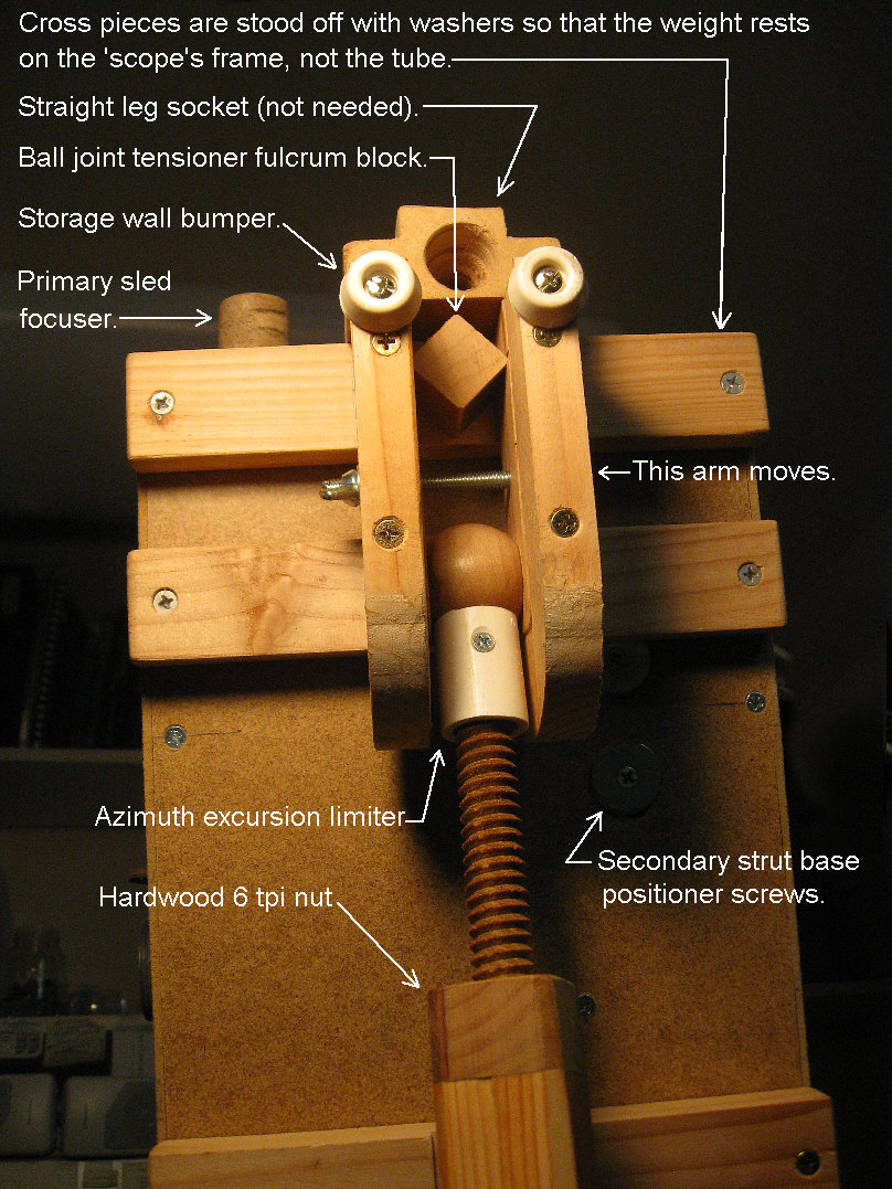
This might be altogether too much work. Next time
I'll try to simplify the wooden extension pole
fore-leg, then screw and lock the top of it into the
U-joint of the commercial sanding block I used
for Dog-1, but I'll still need to somehow brake and
limit the leg's lean-over travel.
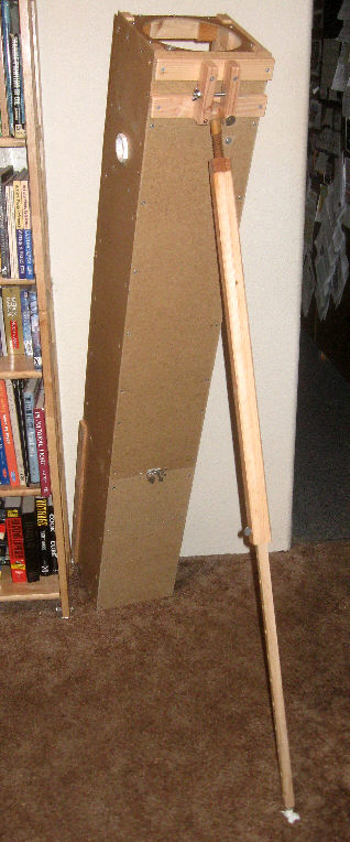
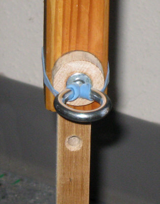
An early image at left (sans leg excursion limiting)
and a recent image of the leg snap set.
The larger leg section is made of two channeled (dato'd)
1x2 furring pieces glued together. The thread "wants" to be a square-ish
3/4" 6tpi ACME, but I used an affordable 6tpi "V" profile tap and die set
instead. The (not very hard) hardwood ball is from an art crafts supply
store. That 1/4-20, mid-leg thumb screw became the (ground down, slips
in to lock the leg) 5/16 eyebolt seen in the right image. A loose fit works
best (in the dark of night).
~~~~~~~~~~~~~~~~~~~
* The altitude can be set from zenith down to 30 degrees
(9/15/2016), at which point I yield my field stool to the scope's butt
end and get down onto a kneeling mat --or: I just wait for my quest to
clear 300 (and the trees).
* Originally, the foreleg was going to be articulated
(folding in half by steps), thus the "dog" name.
* With the scope set up for stool sitting eyeball height
(at 53 degrees altitude), I found that I could turn the thread and track
in altitude from 49 to 62 degrees --and lean the scope in azimuth through
18 degrees.
~~~~~~~~~~~~~
You might ask: "where does one attach the setting circles?"
Well the "DDNU" goes right here:
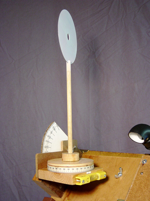
This early Dobson-Dogson Nav Unit attaches with
a single wing nut. The most recent version (2016)
has 4 feet and attaches with a single brass flat-head
screw,
and is meant to stay atop the telescope's OTA.
The DDNU's altitude readings are not dependent upon
the scope being leveled --until you're near the zenith,
then I keep an eye on that extra level (below image).
With this early DDNU version, you start by
getting the current alt-az of Polaris (or maybe a
radio
tower), sight Polaris with that disk, calibrate the
circles
to read true, then go after your quarries --back-sighting
on Polaris for the azimuth. (Arghhh: I went to a magnetic
compass.)
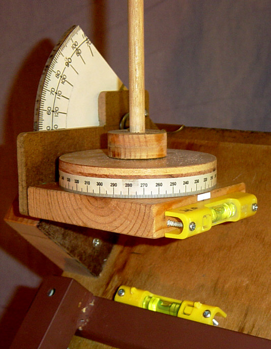
(10) That second level is for navigating
at higher altitudes and/or finding somewhat level
ground.
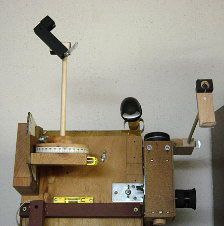
Before going with a magnetic compass, I replaced the white
CD sighting disk with a more sensible 2nd finder (which could still be
aimed horizontally for aligning on something like a radio tower --which
might require a step stool).
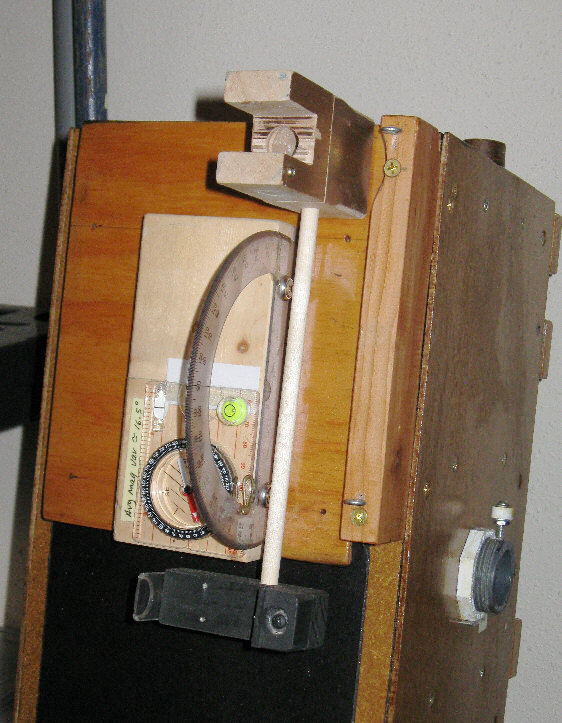
And finally: a magnetic compass --along with a swing-out
glow finder (seen here on Dog-2).
With the glow finder stowed I sight through that pair
of fixed eye screw rings, get a bright object centered in the eyepiece,
then swing out and aim the glow finder (which usually needs a bit of adjustment
at the begin of each session). Those eye screw sights keep me from having
to grovel on the ground in order to sight along the OTA.
* A helpful addition to the problem of "finding"/aiming
has been a new 32mm Celestron Omni eyepiece --affordable and as much field
of view one can squeeze into a 1-1/4 inch focuser. Its light gathering
is somewhat crippled by my 1-1/16 inch diagonal, so it might be 50% dimmer
at the edge, but the 40 power 1.25 degree actual field is all there. My
old 25mm Plossl (Surplus Shed "500" series) only passes a 0.84 degree field
(75% illumination at the edge).
* But: It was still too much
of a reach, 'twixt aiming with the glow finder, then re-centering my quarry
with (say) a medium power eyepiece --perhaps troubling with a return to
the lowest power eyepiece. So: bite the bullet and build me another optical
finder, like I did for Dog-1 --but this time, making a much better job
of it.
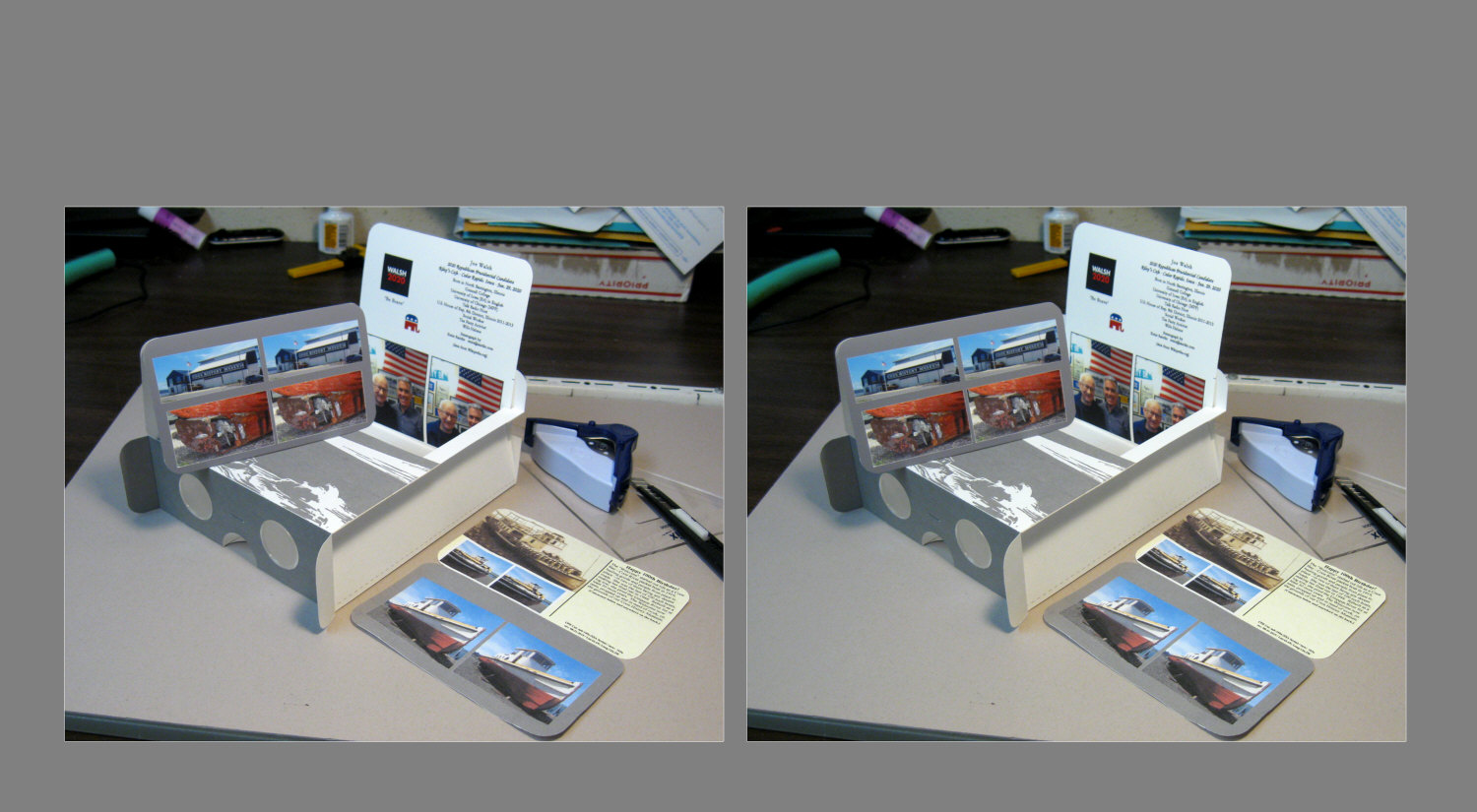
"Free-view" this stereoscopic
pair.
Next, after spending a few frustrating minutes out
in the dark with a phillips screwdriver, I replaced two of those screw
adjustments (focus and azimuth/lateral) with fimger-able knobs:

Final(?) Dog-2 and finder configuration
* The old glow finder is seen here swung around to
the other side (and inverted) --in its secondary role of guiding Dog-2
(me standing and peering through it on the other side) for a guest observer.
As you might gather from the earlier free-view pair,
the glow finder's become a head bumper when used on this side of Dog-2.
I could simply shorten its arm, but (so far) those glow painted open sights
and the new finder 'scope seem to be sufficient.
* Also "so far", I'm not bothered by my finder's mirror
reversal.
~~~~~~~~~~~~~~~
* I need a lot of help when trying to find and track
stuff, so this new finder is for field recognition, centering and recentering.
I should now be able to recover at 10 minute intervals or longer, using
a pointer^ at the eyepiece's focus:
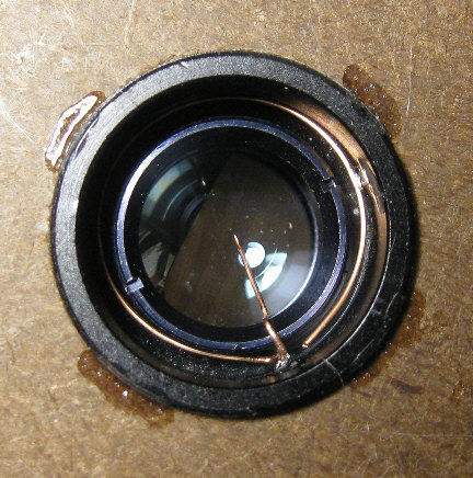 ^ .020"/24g wire (from a piece of old 3-pair, "Cat-3"
telephone cable) --looks rather thick as a reticule (1.37 apparent degrees,
10.6 arc-min actual), but it's delicate enough to work with and secure
in place --without resorting to yet thinner wire. I used a needle nose
pliers to squeeze its points-at tip down to a much narrower dimension.
^ .020"/24g wire (from a piece of old 3-pair, "Cat-3"
telephone cable) --looks rather thick as a reticule (1.37 apparent degrees,
10.6 arc-min actual), but it's delicate enough to work with and secure
in place --without resorting to yet thinner wire. I used a needle nose
pliers to squeeze its points-at tip down to a much narrower dimension.
* This finder's design resembles Dog-1's
finder, but it's much better and mounts flat against the 'scope's OTA
--hopefully to remain permanently aligned and focused.
* Inside, of course, is a 45 degree cut piece of oak,
which mounts an old Polaroid camera's front surface mirror. The top/outer
panel moves in relation to that mirror mount block to optically center
the eyepiece leterally/azimuthally, then the block and the top panel move
together for sharp focus. Both of those adjustments and the adjustable
base plate to OTA attachment get locked with sheet rock screws through
those copper penny "fender washers" (out of deference to the magnetic compass'
environment).
* For reference, my typical looking "Jason/Empire"
8x40 binocular had a screw-in objective barrel with a focal length of 165mm,
for a focal ratio just over f/4. (I left the rest of that old binocular
intact.)
* The oddball (1.20 inch barrel, looks like a Plossl,
came with a bag of stuff from Goodwill) --Japanese eyepiece measures 21.3mm
in focal length with an apparent field of 43.6 degrees, so I should get
an old man's 5.16mm exit pupil, 7.75x power and an actual field of 5.63
degrees. (The binocular was rated as having a 6.5 degree field, which is
what I measured.)
* It's nice not to have to worry about the size and
shape of a refractor's "secondary", but I expected the mirror's reversal
to be less nice --to use as a primary finder. (I'll use those open sights
and alt-az navigation settings first.)
~~~~~~~~~~~~~~~
There's a little cover for the glow finder's lens,
which otherwise dews up quickly, and I've rounded its sharp edges. In use,
the glow finder usually ends up above my head when deployed and I've yet
to so much as bump it (previous to adding the new optical finder). This
configuration seems natural to use --just turn my head and look.
During a session on the night of 6/4/2016 UTC, the
spirit level altitude indication was within 1/3rd degree, but my compass
was off by 8 degrees on one object (Jupiter). Nearly all the hardware in
the vicinity of the compass is brass. Maybe I need to degauss what's not
(mainly: Dog-2's diagonal strut).
The sky-ball approach (using just the device on
the left):
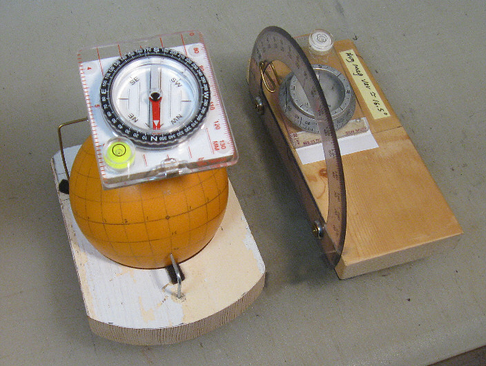
--requires a fairly heavy ball and seems hard to work
with in the dark. (More)
* While the level based altitude indication is accurate
enough, finding the azimuth with any of these devices has been difficult,
so why not simply use the imprecision of a magnetic compass (with a minimum
of ferrous metal screws and whatnot in its vicinity)?
* Yes: something like a GPS, a Celestron "SkyScout",
or a "Safari" ap'd i-whatever would probably work well, but I'm trying
to use low-tech methods --that I understand, can make, and maybe improve
upon.
What finally made the Dogson practical has been its finders
and a widest field (1.25 degree) eyepiece. Getting an object into the eyepiece's
field of view with a conventional finder or manual setting circles can
be difficult, especially in that "low power" use to be 64x and 0.84 degrees
for Dogson-1. For direct finding I start with the open sights --and maybe
with the luminous (glow paint)
collimating finder:
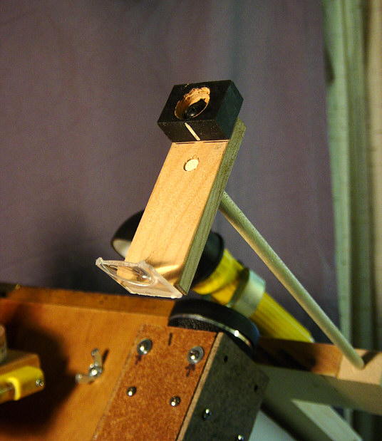
The paint got replaced by "glop" film from "Scope
Stuff",
which is 100x better. This is similar to a 1952 design
by Stanley B.
Rowson, but also in the vein of
"points at" type
finders made by my friend Chuck.
--and just below it in the above photo was a finder
scope with a 6 degree field made from a binocular objective, a rectangle
of front surface mirror, and a 20mm Plossl ocular with a home made copper
wire "points at" reticule:
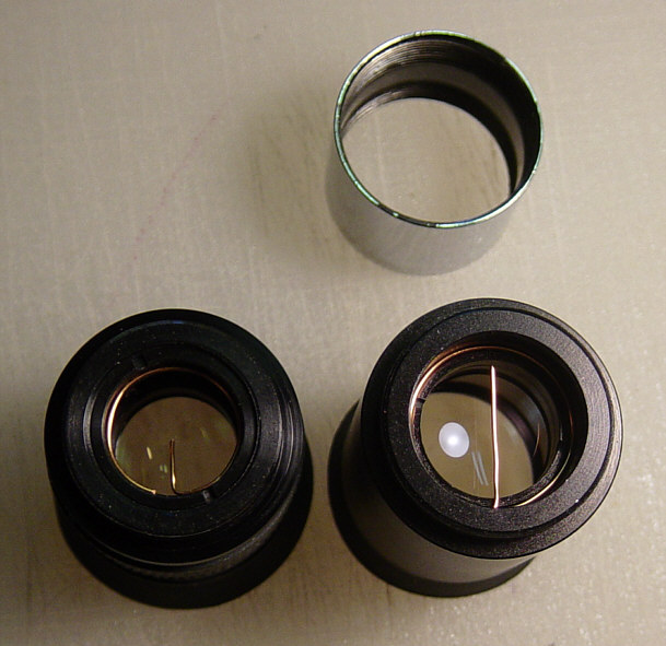
At left is the finder's Plossl with a #24g wire
pointer. At right is a 25mm Kellner with a straight-
across wire reticule, for timing the passage of stars
and
extended details (which has since become an "X" of
two wires).
With the 6 degree finder as an in-between step, it
was pretty easy to nail an object in the sky, but Dogson-2 started out
with just a glow finder (and with the ability to swing it around to the
other side --for guiding the scope while a guest is observing). What (almost)
made that work is a 32mm Plossl ocular with a 1.25 degree field. It's about
one magnitude dim at the edge (due to the one inch diagonal), but that's
plenty good enough for bringing the quarry to center.
* Extended comments 1: >
While that copper tubing strut mount for the secondary painted nicely and
presents smooth edges, I found it ever harder to bend and work with. I
consequently went to a 3/16 inch steel strut, but this time presenting
a curve to the optical path (to eliminate diffraction "spikes"). It's mounted
from the bottom of the tube, so as to keep it more away from the DDNU's
magnetic compass over the top panel.
> Dogson-1's oversized square tube worked out quite
well with room for convection vents, wiring (but no more battery/electric
stuff for Dog-2 and beyond), a mirror cell sled arrangement and a
long threaded rod for moving the cell sled back and forth (when trying
out cameras, different oculars and focusers). I used Dale A. Keller's "Newt"
program to place and size the baffles. For Dog-2 I decided that I can get
away with just 2 baffles. There are also a pair of top vents, so as to
not force convection currents through the entry baffle and into the optical
path.
> The top side of the second baffle below the secondary
really catches the light and should be treated to something like a black
velvet or a flocked black covering, but the stuff didn't stick to my HDF
board. Consequently, all of the tube's interior relies upon the rough backside
surface of HDF and a good coat of flat black oil based paint (brushed on).
> I originally decided upon an f/9+ telescope because
a 6 inch mirror can be finished sphere and still be about 1/10th wave away
of perfection. (A 6" f/8 sphere is about 1/8th of a wave from paraboloid.)
However, when David made the mirror for Dogson-1 he troubled to fully correct
it :-) Since giving this scope away (to become the "Buddsonian"),
I've been given another 6" mirror plus I purchased 6" blanks for making
Dog-2, which I also figured paraboloid --having been persuaded that even
at f/9, on a really good night, a spherical 6 inch mirror can noticeably
fall short of one that's been figured. Besides: the height of the eyepiece
seemed too tall for kids and shorties at f/9, so the aim point became a
more traditional 6" x f/8 (or so) scope.
* Here's a chart showing how
"gudenuf" leaving a mirror sphere can be:
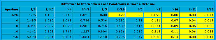
Thanks to "Telescope Nut" Jeff Baldwin.
* Another consideration is the
"sweet spot", and how critical collimation becomes with a short focus scope.
f/9+ is really to be preferred, but I think f/8-plus is still manageable
with "eyeball collimation".
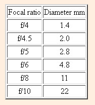
The "sweet spot"
--thanks to Gary M. Bloom's (now missing) web page:
"The Perfect Telescope"
Glow finder comment 2: The
plastic half-lens' optical center is level with the pointer and top of
the target block, but is cut off 1/8th inch higher, such that the phosphorescent
pointer's image (projected at infinity onto the sky) easily clears your
line-of-sight over the block. The blunt point is about 1/3rd of a degree
wide --as projected. Mine is made from amazingly bright and long lasting
glow film^ that I got as a sample. It's otherwise to be had from ScopeStuff
as their "Glop" product. The next versions will probably use a "pointless
arrow". See here for the view through it, and
here
for a drawing and prior art.
^ If you (ever so sensibly) wear a headband mounted
flashlight, then the pointer need not be phosphorescent. Just set your
head lamp to dim.
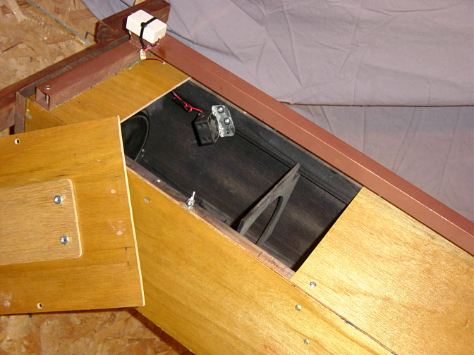
One of the nicest features of Dogson-1 and 2 is having
a back door for easy access to the
mirror --which gets removed after each session to
a "SnapWare" sealed container with desiccant
(and a monitoring hygrometer). (That lesser door covers
a hole through which a fan once
injected outside air into Dog-1.) **Click
here** to see Dog-2's slide-off access panel.
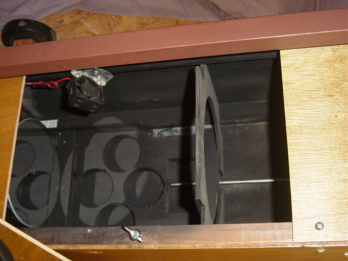
The mirror cell sled is moved by turning the
threaded rod stock --seen on the floor of the tube.
The
sled carries the rear-most baffle and positions the
mirror
via the usual thumb screws in back (but the mirror
is held against
them only by gravity), as it rests on two one inch
dowels. The
dowels are held in place by screws which are about
1/8th inch
eccentric, such that the mirror can be centered in
the tube by
turning the dowels. Spring clips locate the sled as
it moves.
* Dogson-2 also has centering dowels, but uses a 6tpi
wooden threaded rod.
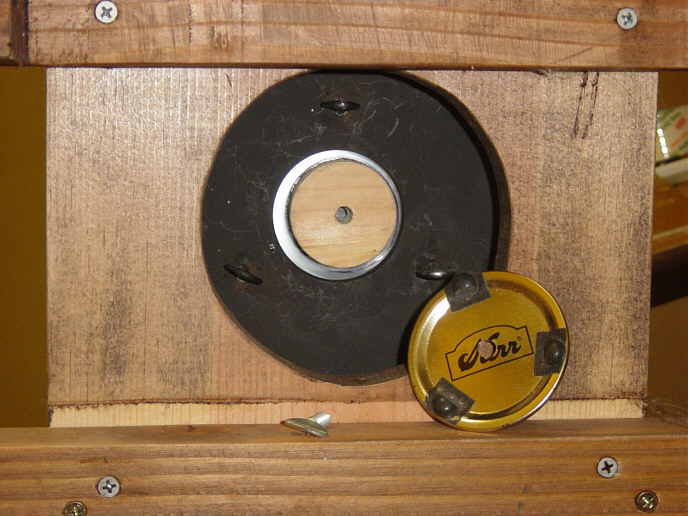
This view of the bottom of the scope and the
back of the mirror cell reveals that a wooden puck
is glued to the mirror's back with dabs of silicone
rubber. There's a 1/4-20 T-nut in the other side of
the center hole which accepts the thumb screw which
holds that canning jar cover in place--
--and thereby holds the mirror captive to the
cell
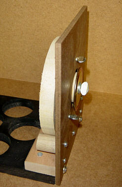
(This early cell-sled design isn't nearly beefy enough.)
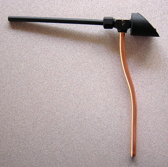
The secondary's copper tubing strut
mount at least looks nice and has a smooth
profile in the beam --
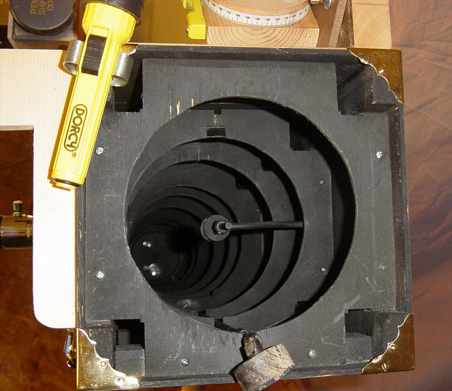
--and it took paint nicely, but I've gone to a doubly
curved
3/16" steel strut for Dogson-2. Also: that universal
joint has been eliminated and it's just the knob now
(for turning the threaded rod which moves the
mirror cell-sled), and it got moved to the left corner.
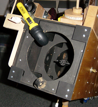
Later on the pretty brass corners got replaced with
these sensible corner
baffles. In this photo the elbow light is shining
light pollution down into the
tube, providing some background light for my non-illuminated
crosshair
reticule --for when all that baffling worked too well
and our normally ample city light
pollution and haze cover was insufficient.
I've officially designated the current Dogson project
"DHS-2" in recognition of the resourceful guys, Holcomb and Sellers who
originated this type of telescope. (Holcomb's was a diagonal-less Herschelian).
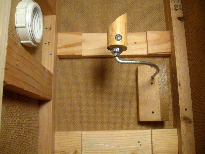
Dog-2's diagonal is supported by a positionable float
block and the whole of it gets involved for collimation.
I doubted that secondary vibration would be a problem,
but
that gap between the nuts carries a dampening washer
anyway --
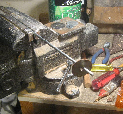
--and you might like to try this experiment to see
how effective a loose washer can be at stopping
vibrations. (Far better than a dangling loose chain).
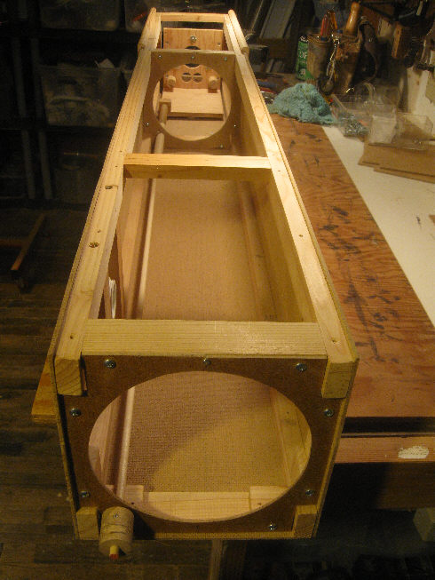
Here's the unfinished interior of Dog-2 (only two
baffles this time).
Here's how the "glow finder" works:
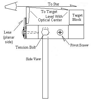
This type of glow finder was first described by ATM
Stanley B.
Rowson in 1952 (*click
here*)
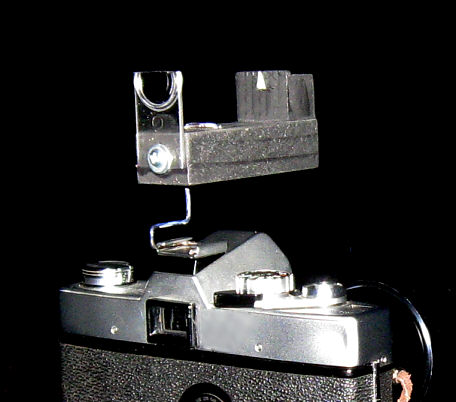
Here it is with a wire mount --on my old Minolta SLR,
--and here's what you see:
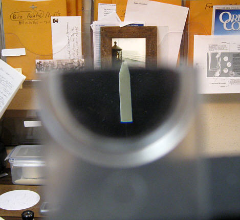
--with the phosphorescent pointer "jumped up", superimposed,
and locked on a distant target.
Aluminization
8/17/2015: A seemingly inevitable "hobby killer" which
we all face --the more so as average amateur mirror sizes and shipping
costs increase, is getting a finished mirror aluminized, or recoated. I've
thought about this at length (and haven't we all) in search of alternatives,
but (as yet) to no avail.
Cleaning the mirrors
10/31/2021:
Our old (30 years) Coulter 13 inch mirror was in bad
shape, so I tried more casual cleaning techniques --
* Having on hand:
~ A bathtub (since I proposed to clean the mirror in
the telescope).
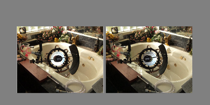 ~ Take off your long sleeved shirt.
~ If cleaning "in-situ", vacuum off the skeletal (strut
type) OTA.
~ A hose, with or without a sprayer head.
~ A pitcher of water with a good shot of Dawn dish
washing detergent.
~ Distilled water ("steam process").
~ Unscented paper towels (clean-ups) and unscented
facial tissue (for blotting) --or just use the toweling and do not rub.
1) Tilt the mirror safely/securely fairly on edge (or
leave it in the skeletal telescope and lower the OTA --per the illustration).
2) Hose the mirror down and at length --fairly blasting
it to remove surface dirt. (Room temp water would be nice, but I just ran
the cold.)
3) Untilt the mirror face up and level --level enough
to hold water to the edge, and pour in the soapy water, letting it sit
a minute.
4) Hose blast it off and soap water again, letting
it sit while you vigorously wash your ends --until your finger pads are
soft.
5) Reach in and (OMG) wash the mirror face --with a
light touch. (You can feel any gritty stuff down to 50 microns. If so,
stop and flush.)
6) Your fingers squeak on clean glass --and that's
clean enough.
7) Tilt the mirror back up again and blast with tap
water.
8) Liberally flush the mirror with distilled water,
which should mostly run off.
9) Blot any remaining water with a handful of fresh,
clean, unscented facial tissue.
10) Blot anything around and over the mirror that might
drip.
11) Leave the mirror tilted up and well ventilated
to thoroughly dry.
12) Then cover it when not in use, but don't seal the
cover, lest moisture collects inside. (Maybe a "shower cap" type food cover?)
13) Notice the ease of mirror removal
I have in my Dogson --and its desiccated, face-down storage box, so that
it never does need cleaning.
The last (12/09/2017) version:
Have on hand: (Blue text is
for something like a Coulter cell and mirror unit.)
* A plastic shopping bag --large
enough to cover the mirror's cell (if duct taped to mirror).
* A bottle of 70% rubbing alcohol, and pour out some
into one of the bowls.
* A bottle of distilled water --and pour out a pint
into one of the bowls.
* A quart jar of large pharmaceutical grade cotton
balls
* A box of unscented facial tissue.
* A number of paper towel sheets (drying hands, spills,
mirror cell, possibly for blotting, but not rubbing the mirror).
* Dawn dishwashing detergent.
* Two clean mixing bowls or kitchen graduates.
* New surgical/examination gloves (to be worn pretty
much throughout).
* Good, bright lighting.
* Black electrical tape and 3M
Scotch tape
~~~~~~~~~~~~~~~~~
0) Remove the diagonal/mount (if it needs cleaning
--usually not), primary cell and mirror from the OTA. (Separate them --or
don't --if it's all duct taped together.)
1) Lay out all your materials onto a nearby table that's
covered with paper toweling.
1b) If the mirror is held in place with clips, This
is a good time to make sure the clips aren't too tight.
2) Cut off the top of the shopping
bag squarely (so as to eliminate the handles).
2b) Open and place the bag on
a level surface. Lower the cell onto it (mirror up) and raise the
bag up to the mirror's edge, pulling it around the cell (assuming it's
duct taped to the mirror --or that you just don't want to remove the mirror
from the cell) and snugly fitting the open end around the periphery of
the mirror, using short pieces of "Scotch" tape to secure it, with the
excess folded over and taped down to one side (about halfway up the mirror's
edge).
3) Finish up by sealing the bag
in place with one overlapped turn of black electrical tape. Take
care not to run the tape too close to the aluminized upper edge/face of
the mirror. (If the mirror is held with clips, be sure to
dry any water that gets under them after the final rinse and blotting.
4) Use a laundry tub or a large enough sink, with a
hand sprayer. Scrub and rinse it --spray head and faucet handles as well.
4b) Place a plush towel into the bottom of the tub
such that it's folded over where the mirror will rest upon it. The idea
is to somewhat over-hang the mirror's face or to lean it back a bit, allowing
water to freely run off. Be sure the drain is not blocked. You might
choose to simply hold a small mirror --like my Dogson's 6 incher.
5) Pour out a cup of alcohol into one bowl, mix a quart
of water (ambient temperature) and about a teaspoon of Dawn into the 2nd
bowl. Pour a pint of distilled water into the 3rd bowl. Set out your
cotton balls, wads of facial tissue and a handy waste receptacle.
Have a few sheets of paper towels stacked and ready to grab..
6) Put on your rubber gloves and lower the cell-mirror
assembly sideways into the tub, such that the mirror's surface is vertically
on edge --resting on the folded over portion of the towel and securely
leaned back, such that you can see it's surface with good bright lighting.
7) Play/spray ambient temperature water onto the face
of the mirror, dissolving and pushing off what dirt it will remove. (Not
very much, in my experience.)
* Some advise to "soak" off dirt and grime, but I don't
think it's a good idea to prolong this or the other steps beyond a few
minutes. I get the impression that the reflective coating can be a bit
hygroscopic, especially if the overcoating is no longer intact. In any
event, you should attempt to keep the mirror fully wet or fully dried.
8) Keeping the water running, the spray head deployed
and handy, completely wet a large cotton ball in the Dawn detergent solution,
then lightly wash the mirror with it, using a gentle, backward rolling
stroke/swipe. Discard the ball before you completely turn it over-around
and start in with another.
* It's critically important that you initially roll
the ball in a direction opposite the ball's travel, such that removed dirt
is immediately and continuously rolled up and away from contact with the
mirror's surface. Subsequent cleaning might be done with one "side" of
a cotton ball per single stroke. (I get 3 such "sides" per ball.)
9) Immediately rinse off the mirror with the spray
head.
* Does it look clean already (or as clean looking as
it's likely to get)? If not, repeat steps 8 and 9. Any grime
or greasy "smear" should come off. Caked on deposits might take 3 soap
sessions --and you'll probably have to gently swab (not scrub) to get the
mirror clean. (You might read elsewhere about "using only the weight of
the cotton ball" or some such. That's not likely to do the job.)
9b) Grab a fresh cotton ball, wet it well with 70%
alcohol, and swab --which might get any remnant crud which answers to alcohol
solvent.
9c) Do another wash with a Dawn soap solution soaked
cotton ball. (Alcohol is otherwise very clingy and stubborn to dry directly,
whereas distilled water beads up nicely and mostly runs off a very clean
mirror.)
10) Completely wet a fresh cotton ball in distilled
water and very lightly rinse the mirror with it. Do this several times
with fresh balls.
11) At this point, and holding the mirror with one
hand, pull off the wet glove from the other (with your teeth), then dry
by blotting/pressing with wads of facial tissue, using your dry exposed
hand. Quickly follow with fresh tissue wads.
* Spots of water can be tenacious. Designed to
be absorbent facial tissue is essential. Gently wipe/brush to dry only
as you have to --but be quick enough about it that droplets are not allowed
to dry by evaporation.
11b) Rest the mirror on its back, remove the other
glove, grab some paper towels and start blotting/wiping off the side and
back of the mirror. When dry, rest it on its back and place a sheet of
fresh stationary over its face.
12) A clean dry mirror accumulates static electricity
and dust --like a magnet draws filings. Don't fret. Simply use a small
squeeze-bulb air puffer (not your breath) to blast it off (which, of course,
imparts more static electricity). A camel's hair lens brush also
leaves static electricity --plus it tends to smear and sleek older mirror
crud. (In the bad old days we could buy a radioactive darkroom photographer's
negative brush, which would discharge the electricity. I believe
they used polonium --arghhhh.)
* The physical moves of dropping in and removing the
primary (to its sealed and desiccated box) has gone swimmingly.
* Presumably, such an approach, or maybe an arrangement
for placing an air tight desiccated cover over the primary of a larger
telescope, could preserve a silver coating indefinitely. The Reverend Ellison
(pages 102-103 of ATM-1) reported such results using lesser efforts. (The
cost of silver nitrate is quite high now, but so is the cost of shipping
and coating a larger mirror. However, a 6 incher ships and coats for well
under $100.)
* As to mirrors which remain exposed: the advice in
Sidgwick's Handbook, sections 7.2 and 7.4, runs opposite our common practice
of only washing a mirror when it's become ungodly dirty. The recommendation
is to preventively wash an aluminized mirror with detergent ("Dreft")
--maybe every 2 months --especially if near the ocean --and even if it's
a silicon dioxide over-coated mirror.
Again, here's the mirror/cell
compartment access:

--and how the mirror is held in place by one thumb
screw (dummy mirrors in these photos). The current cell sled is far more
robust, but the mirror is still located and collimated by gravity versus
3 solder-tipped thumb screws and 2 eccentric support pegs:
--and here's where it's kept when not in use --along
with a handy pair of white cotton gloves --but the mirror is placed face
down (now) and that dark inner lid isn't used:
This "Snapware" keeper contains desiccant and a thermometer-hygrometer
unit which displays its high-low memory. The keeper is stored in my unheated
shop, so the mirror starts out only a bit above outside temperature. That
blue surrounding the mirror is a smooth, aperture defining, square cross-section
O-ring. It covers 3 un-aluminized vacuum chamber support marks and is held
in place with a paper collar. This is probably a good idea, even if you
have nothing (like a turned down edge) to cover up.
* There use to be a wrapping paper for silverware
and plated silverware, "guaranteed to prevent tarnish". My copy of "Fortunes
In Formulas" sez it's made by dipping wrapping paper into a solution of
sodium hydrate and zinc oxide. This might be worth looking into, should
you attempt to silver your mirror at home.
Ocular problems and imaging:
I bought a bargain Meade 26mm Super Plossl "LP" 4000
series eyepiece from the Surplus Shed and it turned out to be an oddball,
specially made for ETX telescopes. The barrel fits loosely in my focuser,
measuring 1.231 inches in diameter (will add some tape), compared to 1.240
inches for the other two standard 4000 SP eyepieces I have. More
importantly, it's probably the only "4000 series" eyepiece that isn't par
focal. I had to back it out 5/16" (8mm) to focus on an object that I had
looking through my Meade 9.7mm SP-4000. Other dimensions (barrel, body)
are different too.
I'm wondering, however, if the "LP" isn't the better
eyepiece anyway. I'll have to repeat my comparisons (and hopefully against
other eyepieces) to be sure, but in my "first light" tests on Jupiter,
there seemed to be a halo --or cone-- of halation around the planet with
the standard lens, which wasn't there when using the "LP". (Update:
confirmed that again with the new mirror -6/5/2005.) I also saw quickly
skittering ghosts --thinking they were meteorites at first. (Update: not
sure of that now.)
** It's important to note that I have an epiretinal
membrane in my right eye, vitreous floaters and deterioration in both,
so it takes me some while to sort out just what I'm all looking at. I don't
use much less than a 1mm exit pupil on account of my eye problems. Eventually
my friends will confirm what I seem to be seeing.
Here's how the two 26mm and my 9.7mm eyepieces compare
in a casual test of their anti-reflection coatings:
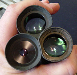 The standard 26mm SP-4000 (from Hardin Optical) is at
top, the "LP" version (from www.surplusshed.com) is on the right. At this
angle (to an overhead incandescent trouble light) I see more and brighter
reflections in the "LP" 26mm. The two standard 4000 series oculars have
similarly colored reflections, the LP looks greenish-brown by comparison.
It appears that the eye lens of the LP isn't black edged.
The standard 26mm SP-4000 (from Hardin Optical) is at
top, the "LP" version (from www.surplusshed.com) is on the right. At this
angle (to an overhead incandescent trouble light) I see more and brighter
reflections in the "LP" 26mm. The two standard 4000 series oculars have
similarly colored reflections, the LP looks greenish-brown by comparison.
It appears that the eye lens of the LP isn't black edged.
By turning this threesome a wee bitty: the standard
26mm shows a bright, full scale reflection flash. Must be a plano lens
surface in there someplace (uncoated?). I can see the same flash looking
in from the field lens too, but I couldn't see any such flash in the other
two, fore or aft.
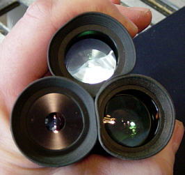 Here's what those 26mm oculars look like under an overcast
sky (the "LP" version is on the right).
Here's what those 26mm oculars look like under an overcast
sky (the "LP" version is on the right).
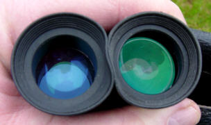 Here's what the 9.7mm SP-4000 looks like closer in --catching
a single 2-tube fluorescent light fixture this time:
Here's what the 9.7mm SP-4000 looks like closer in --catching
a single 2-tube fluorescent light fixture this time:
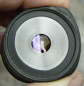 I ordered up 25mm and 10mm coated (they didn't state: "fully
coated") Kellners from the Surplus Shed (see: http://www.surplusshed.com/
I ordered up 25mm and 10mm coated (they didn't state: "fully
coated") Kellners from the Surplus Shed (see: http://www.surplusshed.com/
---for comparison and found them to perform fairly well.
The 25mm is at least as bright, free from halation, and sharp as the Meade
26mm LP, but it does have a faint ghost on bright objects (like Jupiter,
don't see it otherwise) which moves across center in the opposite direction
of the primary image. I didn't think their 10mm Kellner was nearly as good
as the Meade 9.7mm I have (which doesn't have any halation or ghosts).
I'm tempted to order the Surplus Shed 25mm Plossl, as well as two more
25mm Kellners --which have a nice field stop landing for home-made reticules.
The Sky Compass:
At left is a ball based equatorial "Sky
Compass", recently following the two
from 30 years ago, none of which have I used in earnest
--just tested them to see if they worked (yes).
* The alt-az Sky Compass is the type which got used
(with a better compass and spirit level) and it worked fairly well --especially
for the altitude setting. It needs that 360 level for steering to high
altitudes. It (of course) also needs a sky program application and a computer
--if only as some sort of a hand-held digital device.
* The ball type steers to the local hour angle and
declination of an object, such that it might be used with a sidereal clock,
and without resort to a computer^. (Just any clock set to sidereal time
for the night will do, since it would lose only 10 seconds per sidereal
hour.) ^These equatorial sky compasses plus the 'scope amount to
a torquetum: an analog computer.
The results of using various common
eyepieces with various Newtonian telescopes
* For a good introduction to eyepieces, see Doug
Tanaka's Web page at:
> http://bpastro.org/astronomy/amateur-astronomy/selecting-eyepieces
--^
^ However, I feel compelled to rewrite and extend his:
"But medium-powered eyepieces produce exit pupils that range from 2
to 4mm in size. Choose one that produces a 2mm exit pupil. This exit pupil
most closely matches the resolution of the human eye: about 60 arc-seconds.
The resolution of a telescope is 4.55 arc-seconds divided by its aperture
in inches. For optimum resolution we need to find the magnification that
will produce an image of 60 arc-seconds, which computes to roughly 13x
per inch of aperture. This will produce an exit pupil of 1/13 inch, close
to 2mm."
Try instead (and I'm being somewhat repetitive to my
"choosing" paragraphs):
"20/20 vision" amounts to a resolution of about one
(1) arc-minute --or 60 arc-seconds, typically with an eye dilation of about
2mm under good lighting. Amateur astronomers are familiar with dividing
a telescope objective's inch aperture into the number 4.55 in order to
get its theoretical resolving power in arc-seconds. While 2 millimeters
(about 1/13 inch) of eyeball pupil diameter, divided into 4.55, gives nearly
60 arc-seconds, and while most observers are said to gravitate toward toward
such eyepieces, the lens of your eye might perform better at a pupil diameter
closer to 3mm, depending on how good your vision is. Find out what's best
for you by spending a lot of time with your telescope.
From the above paragraph and Tanaka's article, you
can see that using a power of about 13x per inch of aperture yields a 2mm
exit pupil, and that 8.5x per inch yields a 3mm exit pupil. (Also, the
focal ratio of your telescope divided into the eyepiece focal length gives
the exit pupil.)
To be clear: an exit pupil of 2mm with (say) a 6 inch
(150mm) telescope aperture yields 75 power --a bit more than you need to
boost good arc-second sky seeing to arc-minute eye resolution --but that's
fine. An exit pupil of 2mm with a 12 inch telescope aperture, however,
yields 150 power --which you might need to comfortably sort out detail
and split double stars.
* A confounding (but intuitively
true) rule-of-thumb: To get full performance out of (say) photographic
film (or a modern sensor, or the retina of your eye), the lens should be
2 to 3 times better. But to get full performance out of that lens, the
film has to be twice as good. And for either the lens or the film to hit
their specifications, the imaged resolution target has to be twice as sharp
--a "vicious circle".
Unfortunately, when our eyes open up wider than 2 to
3 millimeters, more light does get in, but the sharpness of the retinal
image usually falls off, which might even result in star magnitude loss
as their point images spread out into dim, blurry little blobs.
From The Rule-of-thumb, we see that, on a "good night"
of arc-second or better "seeing", one might lay on not 60x of power, but
120x of resolved power (which requires 10 to 12 inches of well figured
aperture) --in order to realize a throughput of arc-minute resolution onto
your retina. (While a crisp 60x image is visually pleasing, your goal might
be to milk out all the available sky resolution.)
In my humble experience, on nearly any cloudless night,
I've been delighted with the brightness, field richness, clarity, contrast,
ease of finding and tracking when using 40x to 60x of power --through most
any telescope. A 6 inch by f/8 telescope with a standard one inch (25mm)
Plossl eyepiece yields a well defined, one degree (two moons wide) field.
Moreover, in the form of a reflecting telescope with a full length "closed"
tube, that's as much telescope as I care to carry around. (My Dog-2
'scope weighs 30 pounds.)
* The following chart assumes:
* The use of either 1.25" barrel eyepieces (maximum
field stop: 27mm) --or
* 2" barrel eyepieces (maximum field stop: 46mm)
--as needed.
I had the opportunity to closely study an 8 inch by
f/6 commercial Dobsonian telescope with a scant round tube of 9 inches
inside diameter (should have been a tad larger). It would have been possible
to use to use a low profile 1.25 inch focuser if the lowest power ocular
is 25mm by 50 degrees. My impression is that any telescope larger and shorter
than a 6 inch x f/6 should be fitted with the equivalent of a 2 inch focuser.
* A diagonal that's sufficient to support the
chosen eyepiece (which might legitimately be significantly "undersized"),
* Either affordable Plossl eyepieces (aka: "oculars")
with about a 50 degree apparent field of view --or
* "Panoptic" type oculars with a 68 degree apparent
field of view, which work well at f/6 and higher.
* Longer ones are made, but 1.25 inch Plossl
oculars with an apparent field of 50 degrees start clipping a maximum 27mm
field stop at 32mm of focal length, Panoptics clip at 24mm. For 2 inch
barrel oculars, that's 55mm and 39mm.
* A 6mm widest exit pupil. (The secondary shadow
might take up 15% to 33% of that diameter, occulting a large
part of your eye's best, 2 to 3
millimeters of core vision. (I downplay reaching your eye's limit.)
* Medium and high power oculars are out of play
here (and would always be 1.25 inchers).
* I've disregarded Newtonian "get the ladder"
focal lengths over about 1500mm.
* It's been suggested (by Doug Tanaka & others)
that most of us can only critically look at about a 50 degree wide
field of view at one time. Jean Texereau
was doubtful about the utility of apparent fields wider than 60 degrees.
* Bolded values indicate some advantage for the
added expense (though you might need a larger diagonal).
* The listed eyepieces don't necessarily exist
in the given focal lengths, so go for the next longer or shorter.
** Please advise me of any errors here --in my
math, awareness, understanding, something missing --whatever.
Big Note: The "Plossl" listings under F/3 are
only be good for theoretical comparisons and about what's do-able.You need
eyepieces designed for an f/3's steep cone of light, as well as something
like a TeleVue coma corrector.
* The best information on short focal length "richest
field telescopes" (RFTs) is on Mel
Bartels' web pages, along with a wealth of other resources. Mel
offers an interactive utility for diagonal sizing and performance, as well
as a telescope planner utility with which you can plug in scores of real
world eyepieces.
If you like the simple "Newt" program and are trying
to go RFT, you'll love Mel's utilities. (Be sure to check out his short
focus, wide angle, very rich field of view, 6 inch aperture telescope,
with which he's been drawing impressions of immense filamentary structures
--which might otherwise have gone unobserved. Some of these may well be
discoveries!)
The you-need-a-ladder combinations have been left
blank.
The diagonal --itself:
Per Oldham Optical's presentations at:
> https://www.oldhamoptical.com/elliptical-flat-quality
--one might use a rather humble piece of plate or even
"double strength" window glass for the diagonal.
* It might still have to be worked in order to minimize
a coarse polish, the "digs and scratches" with which window glass is afflicted,
plus whatever other atrocities the hardware store or you may have inflicted
(say: while grinding or core drilling out an elliptical shape). However,
we see in Ingalls' "Amateur Telescope Making" books that old timers used
selected pieces of plate glass just as it came.
* Oldham's reasoning about surface tolerances doesn't
hold up (and thanks for pointing that out, Mark). His illustration
of surface depth departures (and Oldham does state that such divot steps
aren't real world) aren't (IMO) the main consideration --it's the surface
slopes which result in such depth departures.
 * It still could be that a wave or two of departure from
flat would be no problem in a long focus scope --and that your diagonal
handiwork could be aluminized and overcoated at discount when sent along
with your primary mirror.
* It still could be that a wave or two of departure from
flat would be no problem in a long focus scope --and that your diagonal
handiwork could be aluminized and overcoated at discount when sent along
with your primary mirror.
* The Dog-2 project on this page ended up at a focal
ratio of f/8.74, which placed the secondary/diagonal only 10% of the way
back from prime focus to the primary mirror. Reason and intuition then
suggests that as much as a wave of error at that point would only contribute
what 1/10th wave of error in the primary's surface would produce.
Surface roughness (lack of polish, "scratch and digs"),
depending on their degree and dimensions, might contribute much more or
less in terms of light dispersion and contrast loss. "Wave" error dimensions
are more about the average surface.
* I think there's more prospect in cutting down an
existing front surface mirror --by donning cotton gloves and carefully
cutting out a rectangle of the right 1-to1.4 size, then "nibbling" the
corners off as well. (You'll get diffraction spikes if the diagonal isn't
smoothly elliptical --and its supporting strut curved, but some astronomers
like and make use of such spikes. Alternatively, a somewhat over-sized
wooden mounting plug could also be used, such that the primary sees its
shadow instead of the diagonal's --and at very little obstruction cost.)
Amateur Telescope Making Book One has a good
description on page 55 of how to go about deducing which of three prospective
pieces of glass are flat (but I suggest that you use small paper spacers
and minimal pressure, rather than to "wring" pieces of glass together --like
a machinist's set of Johanson blocks).
** Then there's the thorny issue of sizing the diagonal
--!
~ For a general purpose telescope, the diagonal is
often made "undersized", which means that it limits the light to the edge
of the lowest power field of view. Obviously, this depends a lot upon the
eyepieces you intend to use, and how large an exit pupil your own eye can
make use of (7mm if you're young, maybe only 5mm if you're old).
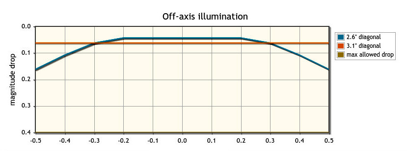
A diagonal performance graph, generated by a utility
at Mel Bartel's excellent
web site.
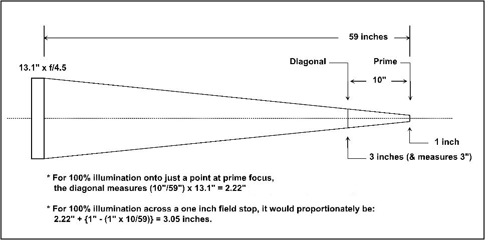
The same 3.1 inch diagonal, ray traced and then calculated
for size
(click to enlarge)
~ The luminosity profiles from Mel's web site shows
the trade-offs for diagonals which might be fitted into an old 13.1 inch,
f/4.5 Coulter (brand) "Odyssey" telescope. The smaller diagonal delivers
a bit more light to the 1/2 inch core of a 1 inch (and 1 degree) low power
field because it blocks 2% less light. The outer portion, however (which
is 75% of the field by area), falls off by 15% or so. Were you to be visually
going after wide fields of faint nebulosities with this scope, you might
prefer the flat-across brightness of the larger diagonal.
~ However: if this were intended to be a "planetary"
scope, used at higher powers, the smaller diagonal would be ample for the
field of a higher power eyepiece. It's smaller obstruction should also
allow of better contrast and resolution.
~ There's yet another important factor/trade-off: the
diagonal's shadow to your eye. Used with (say) a 32mm (47x in this Coulter
scope) eyepiece, you get a 7.1mm exit pupil --consisting of an image of
the primary mirror and the diagonal's obstructing shadow. If you
went for the 3.1 inch diagonal, its shadow is (3.1/13.1) x 7.1mm = 1.7mm
wide --and that's the best part of your eye's core vision. (Some say your
best eyepiece for critical observing is one delivering a 2mm to a 3mm exit
pupil.)
* This last factor favors traditional "long focus"
(f/8+) telescopes, since diagonals can be smaller: maybe only one inch
in a six inch aperture f/8 (although such a scope can't practically reach
a 7mm exit pupil, with affordable 1.25" barrel eyepieces).
Refractor telescopes:
* If (say) a 6" refractor is within your resources
(to build or to buy), then the eyepiece/field stop, and any ("star") diagonal
can be as large as might be convenient. There's no "secondary shadow" as
a consequence nor any secondary support spider spikes.
As to affordability and ATM-ability, an achromatic
doublet objective is probably the "working class" limit, and that means
long
focus --perhaps as long as f/15 --and a "long tall sally" OTA, tripod or
peer. Fortunately, that doesn't mean standing on as tall a ladder (ala
an f/15 reflector), and while OTA rigidity is nice, it's not critical,
since the prime focus "sweet spot" is huge.
Be my guess: the ATM might consider building the low
power ocular as well (using recycled 35mm film camera lenses?) since I'd
expect an off-the-shelf huge eyepiece to be hugely expensive.
* One of the show stoppers for such a project would
be getting anti-reflection coatings on the 4 surfaces of the objective.
But might that be skipped? Previous to World War Two, artificial^ AR coatings
were considered to be a military secret, so even professional astronomers
didn't have them. Once upon a time I shaped and sold uncoated lenses for
the stereoscopes I made (later with Luther Askeland) and as accessory lenses
for stereo cameras. Neither I nor my many customers noticed reflections.
(I did blacken the lens edges for better contrast.)
* A killer show stopper would be met in trying to grind,
polish and test the 4 surfaces. Although each of those surfaces are spherical
and much less critical than a reflecting telescope's primary mirror, you
can't rough up the "back side" as you grind and polish the second side,
the 4 optical centers/vertexes must closely agree when you're done, and
although you'd carefully ground the 2 surfaces of each lens parallel at
the start, good luck on them staying that way.
* The last price I've seen for buying the 2 blanks
and 4 tools was in the $500 to $600 range (Newport). The last price I've
seen for purchasing a fully coated f/15 achromat, already mounted up in
a cell: $500 to $600 (Istar Optical).
* Then there's getting your refractor rig out into
the field and using it. Best you first go to a star party or go out observing
with a friend who owns a big (6"+) long focus refractor and see how it
goes. Unless the owner has gotten the focuser close to the altitude (or
equatorial) bearings with counterweights, the eyepiece is really going
to move around.
* On the other hand, there are plenty of affordable
70mm to 100mm refractor scopes and binoculars
to be had which can deliver wide fields and exit pupils.
I note once again that, when you reach a 5mm to 7mm
exit pupil (depending on your age), there's nothing more to see --at that
power. Let's say you're at 10x with a 5 degree field and a 6mm exit pupil.
That's a 60mm objective (against maybe a one inch eyepiece in a binocular).
By going to a 120mm objective, nothing is gained --unless you double the
power and halve the field with a normal 1/2 inch eyepiece. (One might try
a wide angle eyepiece, but at considerable cost.)
Mel Bartels is doing some of his best "IFN" work tracing
faint tendrils of gas and dust with a very short focus 6 inch reflector
and wide eyepieces. (I think he'd do even better with a 6 inch refractor,
but I'm wondering if he could do just as well at lower power [same exit
pupil] and [say] a 4 inch refractor?)
However, for serious power, resolution and stellar
magnitude reach, a longer focus reflecting telescope, built or purchased,
is hard to beat.
* If I haven't talked you out of building a refractor
by now, I suggest that you make the OTA square --somewhat like the plan
in Richard Berry's book (Build Your Own Telescope), but of lighter construction
and with fewer baffles.
^ After many years, camera lenses were sometimes known
to develop a natural patina with anti-reflection properties. Such lenses
were highly prized among professionals. Also, at least one German company
sold cameras with AR coated lenses before the war.
Clocks
* I've gone to a retired
Motorola cell phone (a compact "flip" phone, but old enough to have a pull-up
antenna) which has a very nice voice memo utility, displaying it's sound
files with time-date stamps. This particular model charges through a standard
mini-USB port and shows the time through its flip cover whether on and
illuminated or not (via its high contrast passive display).
Newer cell phones don't need
a contract or prepaid minutes to be very useful. They tell the exact time,
WiFi onto the net, alarm, memo, take photos --on and on. You can pick them
up new for as little as $10. Our TracFones (LG, Huawei, and an older Kyocera)
and the (was sold by Verizon) Motorola are always in synch with the WWV
short-wave time signal --as long as they can connect with a cell phone
tower --but none of them display seconds.
** I think it's also worth your
while to see what your cell phone camera can do as an "afocally coupled"
telescope camera. You should be able to get the photos out of your cell
with a $5 adapter cable to your graphics computer. (If you have no personal
computer, explore doing astronomy with i-Phone or Android applications
like "Safari" (something I have next to no experience with).
** Below is the Swedish "Precision
Planet and Star Locator" planisphere which, besides showing tonight's sky
map, would spit out the declination and right ascension of objects, as
well as your local sidereal time (especially if you had the one made for
your approximate latitude). This is also known as the "Kennedal planisphere"
--for the man who designed and manufactured it.
You can't get these anymore (killed off by digital
sky programs), but a regular David Chandler, double-sided "The Night Sky"
planisphere is a very nice item to have instead.
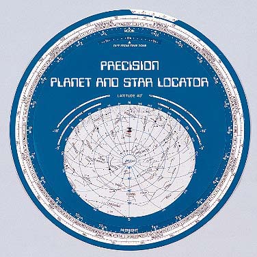
The best planisphere ever !
(This later model Kennedal has "spider web" lines of
local altitude and azimuth, absent from the earlier 1984
version, which is seen when you click for an enlarged
image. One might add such an overlay to any planisphere.)
Here's the alt-az Sky Compass upgrade
for use on Dogson-2:
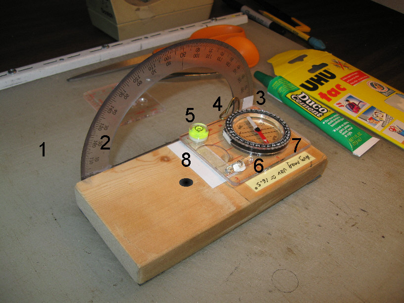 * Start by working on a fairly leveled surface (like my cut-upon
#1 here). You'll need an ordinary drafting protractor (2) and a magnetic
hand compass (7) --in this case: a cut down $8 "Coghlan's" brand via Amazon.com.
(If the needle's sticky, tap it.) I added a laser printed second index
line (no #, slipped under the graduated ring at left) at the local magnetic
variation.
* Start by working on a fairly leveled surface (like my cut-upon
#1 here). You'll need an ordinary drafting protractor (2) and a magnetic
hand compass (7) --in this case: a cut down $8 "Coghlan's" brand via Amazon.com.
(If the needle's sticky, tap it.) I added a laser printed second index
line (no #, slipped under the graduated ring at left) at the local magnetic
variation.
* That piece of glow tape (3) is double-stick taped to
the compass and shines through the drafting compass --as the hand compass
hinges up on 3M brand "V" plastic (#8 --for stopping drafts through door
and window jambs) --and gets held at a given setting by spring tension
(#4 --made from 1/16" brazing rod).
* The small level (6) (which might have to be salvaged
from an inexpensive hand level) sets the 'scopes altitude with good accuracy,
although that small 360 degree level (5) is needed aa you approach the
zenith --and to find somewhat level ground. Both are adjusted against a
small dab of "UHU" brand office tacky clay, then secured with "Duco Household
Cement".
* All-in-all, the best way to find your way around the
night sky is to learn it well enough (with the help of a planisphere, star
charts, and/or sky programs) that you can "pick" your way around by "star
hopping" with a good finder at low power. The Sky Compass works, but getting
and transferring your updated co-ordinates is slow going.
* Another alternative (for VSOing, say) is to photograph
(astrograph) in the general direction, then find your way and pick out
your stars later.
The Sky Compass, as mounted on
Dog-2 (with its
glow finder in the stored position,
and here shown without the initial open sights):
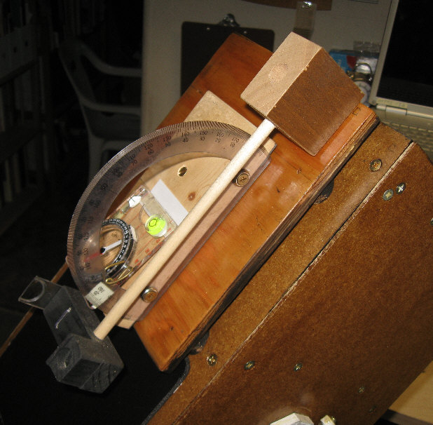
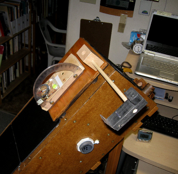
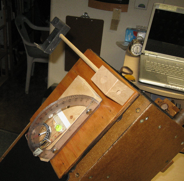

The finder is located such that I can simply turn
my head away from the eyepiece to use it --
or: it can be swung and the taper fit remounted left,
for assisting a guest at the eyepiece. Not
shown is a lightweight, cone shaped plastic dew shield
(a plastic drinking cup) which slides over
the finder (and to prevent getting poked in the eye).
My favorite
astronomy and ATM books/resources:
* The Backyard Stargazer (2005)
by Pat Price
** Scientific American's "The
Amateur Astronomer/Scientist" from the Surplus Shed
The Telescope Handbook and Star
Atlas (1967) by Neale E. Howard
The Guide to Amateur Astronomy
(1988) by Jack Newton and Philip Teece
Burnham's Celestial Handbook
(1978) by Robert Burnham, JR.
How To Make a Telescope by Jean
Texereau (1957 --there are later additions)
** Amateur Astronomer's Handbook
(4th Edition) by J. B. Sidgwick (revised by James Muirden)
Amateur Telescope Making (4th
Edition -1974) edited by Albert G. Ingalls
Making Your Own Telescope (1947)
by Allyn J. Thompson
Astronomy (1913) by Harold Jacoby
* Astronomy by Sir Fred Hoyle

"Keep Looking Up"
(Depiction of an old-time mariner finding his position
by the stars.)
* The original content on these
pages is unencumbered by copyright.
~~~~~~~~~
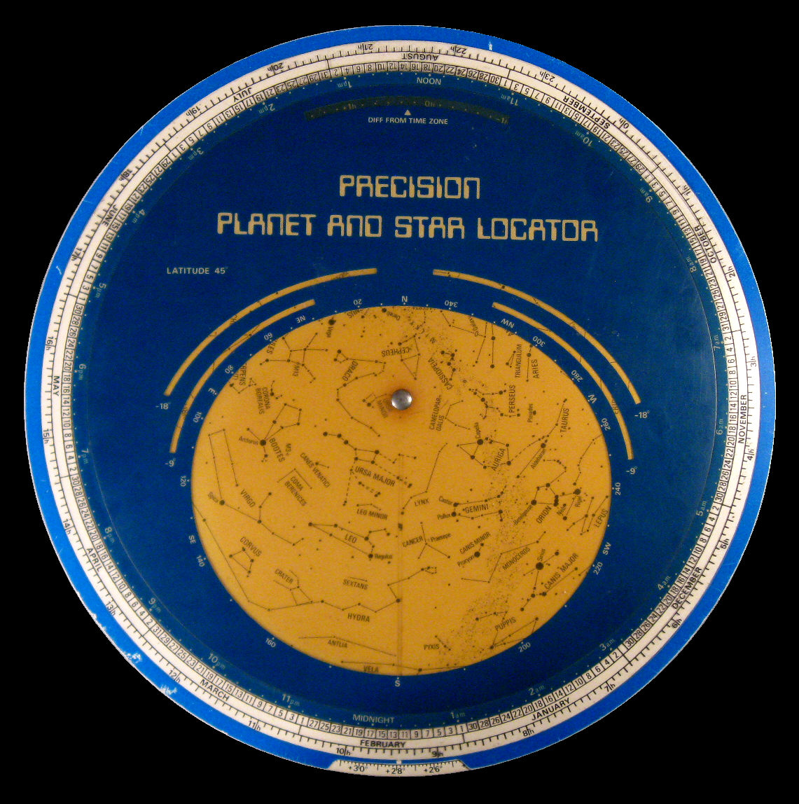
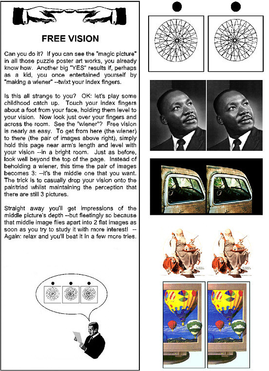