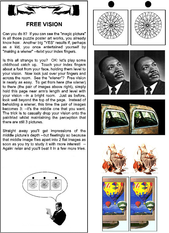
![]()
fastfind>>reversed_window, freeviewing,
main
stereo page, digital trimming,
basics,
template steps, ---How
to turn Fuji-W3 camera images into stereo prints: step-by-step -
This page is intended to answer common needs and questions about composing stereo (3D) views.
Take this link for digital file management (using two digital cameras) plus an extended example of how to trim paired camera and "weight-shift" single camera stereo pairs for vertical registration and window.
If terms like "TIFF", "JPEG" and such are unfamiliar, click *here* for a basic digital graphics tutorial tutorial.
![]()
With this page begins the overly ambitious goal of imparting not only traditional stereographic "trimming and mounting" skills, but sufficient information to take a run at anaglyphy and "Stereosynthesis" --an art form that's older than photography, since Sir Charles Wheatstone had to draw stereo pairs by hand to illustrate his discovery and descriptions of stereo vision. The invention of a practical camera and photography were still a few years off.
The opening salvo here will try to convey the idea of "the stereo window" --via illustrations, the best of which are Dr. Dale Hammerschmidt's --taken from "A Stereo Photo Glossary" (which see for anything unfamiliar here).
It's surprising how hard this simple concept is to get across. Those who do understand the "stereo window" (and no special intelligence is required) --are (despite their own initial problems) --consistently amazed at how hard it is for others to grasp.
 What
we have here is you --standing in a room --whilst gazing out of
a rather small window. When trimming/cropping a stereo pair of images ---we
try to replicate what each eye sees --though just such a window --onto
the world. Each of the two prints in a stereograph corresponds to the view
of each eye --the left-to-right extent of what each eye sees --through
that small pane of clear glass.
What
we have here is you --standing in a room --whilst gazing out of
a rather small window. When trimming/cropping a stereo pair of images ---we
try to replicate what each eye sees --though just such a window --onto
the world. Each of the two prints in a stereograph corresponds to the view
of each eye --the left-to-right extent of what each eye sees --through
that small pane of clear glass.
Obviously: because of the different angle of each eye, they see somewhat different "takes" onto the world beyond the window --because the pane is near and the scene is far.
But we'll let Dale explain it to us:
* Stereo Window (of a view): A basically simple concept that for some reason is not intuitively obvious, and causes no end of confusion to newcomers to stereography. If one views a stereograph, it is generally most comfortable if it is mounted in such a way that one appears to be viewing the three-dimensional image as though through a window. This mythical window is the "stereo window." If one does not mount stereographs in this manner, the edges often have a distracting "choppy" or "floating" appearance to them. The way it works is outlined in the following figures, in what we hope to be an informative manner:
.
As you can perhaps appreciate from this illustration,
an object on the far side of the "window" will appear
to be more to the right in the right-hand image (that
is: have a wider margin on its left side) and more to
the left in the left-hand image (have a wider right-hand
margin). Just the opposite is true in an object which is
closer to the observer than the "window". [end direct quotes]~~~~~~~~~~~~~
When viewing through a window, the right eye sees a bit more to the left --and the left eye sees a bit more to the right. Trimming and mounting stereographs correspondingly will create an apparent "window" through which one views the scene. The most comfortably viewed stereographs are those in which all in the scene appear to be on the far side of the "window". Exceptions can be made for objects which appear to pierce the window pane, as long as they don't cut into the left or right frame edges.
~~~~~~~~~~~~
At left is an example of an object (the blob) which appears to be behind the "stereo window". (Use your small "finger lorgnette" or "free view" to see this pair.)
In life (and as Dale's just told us), the blob appears further to the right --when looking with just your right eye. That's simply because your right eye is further to the right --and distant objects appear to "track" with one's moving point of view --much as the Moon "keeps pace with you" while driving along a straight road at night.
BUT: in picture pairs (designed to be mentally "fused" --seen, each, with just one eye) --this "window pane" eye-shift effect is simulated --simply by trimming the two prints inward on their outside edges --as might be needed* to produce the appearance of a close window. (* Real stereo cameras are designed to clip those edges off somewhat --right on the negatives or sensors.)
Why bother? --Because the picture pair has to stop SOMEwhere --and it might as well be done right --else you'll get scene detail appearing to be cut away and floating in front of the window's frame edges, which results in visual confusion.
Here we see the blob again --but its clearly in front of the window, and yet: there's no problem in viewing it.
Reason: the object/blob doesn't cut the window's edges. It's "reasonable" that the blob can come through the window --as long as it doesn't tear into the window's frame by doing so.
If you measure the distance between the left and the right appearances of the blob (left edge of it to left edge --say), you'll find that this distance is less than when you measure the spacing between the same edges of each window frame. It's now the WINDOW which appears further away --because it appears to be more stationary when your vision shifts from your left eye to your right eye. (Sorry: this "window" explanation might be getting to the point of over-kill for you.)
Computer Stereo: So what's this "side-by-side" print pair business about --when we're working with electrons, screen phosphors, bits and bytes?
An understanding of how the stereo illusion works is essential to your digital ventures --for the image pair is also what you'll be working with when using a computer to create stereo views --even if you turn the pair into an anaglyph. When you render a good pair, only then do you "encode" them into an anaglyphic composite (to be viewed with red-blue glasses).
(* If you've read this far w/o fusing the pairs, either stop and learn how to "free-view" or order yourself up a stereo lorgnette (pair of prism glasses). (Strong reading glasses might not work, since their prism power is inward, instead of outward.)
~~~~~~~~~~~~~~~~
We're a long way of from doing anything like "stereosynthesis" or general stereo drawing at this point. The next step is to get some stereo camera pairs to work with.
I've included a sample that you can work with for now. Right click to save it to your hard drive or diskette.
For more: scan in pairs from prints, negatives, slides --or get a nice stereo digital camera (and I think you really want a Fuji W3).
Again: you'll be working at "trimming and mounting" very much as if you were working with photographic print paper pairs and an Exacto type razor knife, so you might want to first work with actual photographs. I have "mounting steps" and patterns you can use for that --as well as a 2-hour 3D video (by request).
However: doing your "practice cuts" on monitor images costs nothing when you botch it --and you can try all sorts of crazy ideas that might occur to you --without so much as getting mounting glue on your fingers.
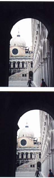
Take "weight shift" pairs with an affordable digital camera
If you're using a regular camera, you probably want to hold it in "portrait" format to make stereo pairs --unless your final output is to anaglyphs (or an advanced shuttered format of some kind). Print pairs want to be squarish or tall.
~~~~~~~~~~~~~~~~~~~~~
--And now you don't!
Since you won't be working on these screens, I've reduced the pairs to an easily fused format.
This stupid looking drawing will help you avoid confusion when I refer to scene elements (--and get you into the frame of mind that drawing stereo pairs isn't all that tough).
I've included this drawing (*t2-07.gif*) and two "untrimmed" stereo pairs
--for you to practice on. Simply bring them into your graphics program (Micrografx's Picture Publisher-3.1 if you can find a copy, possibly: Paint Shop Pro (any version). Then toggle back and forth ("Alt" + "Tab") between your work and this instructional.
. Trimming and mounting standards for "Holmes-Bates" format print pairs.
There's not a lot of agreement on standards, even within the Stereoscopic Society of America --except to say that the subject shouldn't be "cut off" by the "stereo window" --and that the left and right images should be mutually level. Let's consider the issues:
"Window Reversal": * Some critics will say your have "window reversal" if any subject matter is seen to appear in front of the stereo window. However, in this section we show how that can be reasonably done.
* Most people who know stereography will use that term if subject matter is seen to be "cut off" by the window. What that means is: there's an impossible relationship in which subject matter that's clearly (stereo-visually) in front of the window, is never-the-less blocked by the frame of the view's window --a window that appears to be further away --maybe even at the view's "infinity" or beyond.
The solution is to cut away the outer edges of the frame pair: some off the left edge of the left frame, an equal amount sliced off the right edge of the right frame. You can easily mask the pair first to see how much you need/want to remove.
"Infinity Separation": This is the actual (ruler) distance on the card between the same item in the farthest distance in both prints ( which details are called "homologous points at infinity").
Obviously, anything you're able to stereograph is less than infinitely distant, but anything more than 100 yards away is as good as "infinity" in normally stereographed views. "Hyper" pairs can reach out much further in conveying depth, but the separation of those distant points --as mounted on a view card, should still be at your "infinity standard" --for the kind of cards you're making.
When nothing approaching infinity is in the stereo view at all (an interior shot, say), you might want to set the furthest subject matter to less than infinity card separation, but that's not important.
In these illustrations, the Sun is a safe bet for stereo infinity, ya?
While left-to-right distance between similar left-right details isn't something we worry about in anaglyphic views, they begin with good pairs in which this (as well as leveling, "deviation" (stereo content), and "window" practice does.
Normally, you trim a pair for a good "window" (defined by the two frame lines in my illustration --which represent the edges of two borderless photos), then mount them onto the card --such that the Sun-to-Sun distance is within some tolerance.
For use in a traditional stereoscope, old school opinion places that distance at some low value like 78mm (3-1/16 inches), but theory allows a separation up to about 89mm (3-1/2"). For practical use, however, the targeted separation should be about 81mm (3-3/16") --or less.
Now let's relate that to a monitor display.
(Use your red-cyan/blue glasses to view this anaglyphic stereograph.) Instead of approaching life-like "parallel vision" (ie: one's eye's looking straight out into the far distance on a view card or stereo slide pair), we usually make an anaglyphic composite such that our eyes are converged at about the distance of the monitor screen (plus or minus). This produces a visual effect called "puppet theater": miniaturization of the scene in apparent size and depth, but few of us notice or care, since our "mind's eye" judges a view's verisimilitude by its own implicit standards.
So "puppet theater is easily tolerated and even "cute", while side-by-side pairs on a monitor screen or something techie-klunky like liquid crystal shutters can be difficult to control and view. It's my opinion that anaglyphs are the only way to go for good and practical-to-post digital anaglyphy.
Another advantage of anaglyphy is the delightful ease with which such images can be integrated with text --whereas stereo pairs require that any legends near the pair be carefully treated or placed.
So once you've selected your separation and gap, you've also selected your (approximate) print width. The pair can be considerably narrower --often with pleasing results, but it can't be much wider. To maintain your separation standard, narrow print pairs will (of course) use a wider gap.
The height of the pair is up to you: whatever suits the subject and the card stock.
* For working graphics on a computer and monitor screen, we place the pair as close as possible --such that we can work images as large as possible AND while seeing as much pixel detail as possible. That limit is about two 4 (actual-on-the-screen) inch wide images --viewed/fused with an "RCI" lorgnette, but somewhat less is much more comfortable.
You'll probably have to view your pairs at an even 25% (or: "1:4") reduction or even 1:8 --enlarging to 100% from time-to-time in order to fix small details. An odd-ball reduction might end up displaying confusing depth artifacts and "depth jaggies" in your display.
Upon completion, you can spread out the pair for whatever gap you want to use.
--at 50% transparency.
Here I've completed the project by filling with gray at zero transparency, cutting away the excess card area. While this appears to be (and is) two trapezoidally trimmed frames on a card, I think you can appreciate how the frame lines are nothing more (or less) than scene elements. The frame lines describing the stereo window might be circles, ellipses --or even follow the contours of nearby subject matter in a view (which can be eerily effective for impact).
Obviously, some computer graphics programs are far better suited for such fancy work than are a ruler and an Exacto knife(!) --but not all graphics programs.
I'm here to tell you that my first run graphics program was created in 1992 by Micrografx: "Picture Publisher 3.1". So far, nothing's equaled it for intuitive operation and exacting work. It still operates under an XP-3 operating system (and earlier environments), but some of its ability to format compressions are crippled, and some of its advanced features are lamed. I also use PPub-8 for a few features, to export up-to-date JPEGs and other formats.
